Turning and milling composite machine tool

A compound machine tool, turning and milling technology, applied in metal processing machinery parts, maintenance and safety accessories, metal processing equipment, etc., can solve the problems of reducing the working efficiency of bearings and corresponding threaded shafts, consuming a lot of time, and inconvenient maintenance for personnel

Inactive Publication Date: 2021-03-16
王涛
View PDF0 Cites 0 Cited by
  • Summary
  • Abstract
  • Description
  • Claims
  • Application Information

AI Technical Summary

Problems solved by technology

[0002] The most common part of the existing turning-milling machine tool should be the bearing, but the existing turning-milling machine tool often needs to use the motor to drive the threaded shaft to rotate, and then the threaded shaft needs to be installed on the bearing, because the bearing and the threaded shaft When rotating, if the corresponding supporting bearings are not well lubricated and maintained, the damaged bearings are replaced in time, and the parts debris and dust in the external space are prevented from invading, resulting in bearing wear and abnormal work, making the equipment The accuracy is reduced, and the actual working efficiency of the bearing and the corresponding threaded shaft is also reduced. Due to the existence of the above shortcomings, the machine tool cannot continue to work for a long time and personnel need to spend a lot of time to organize and maintain the machine tool. Due to the above The existence of shortcomings makes it inconvenient for personnel to maintain and use

Method used


Image

  • Turning and milling composite machine tool
  • Turning and milling composite machine tool
  • Turning and milling composite machine tool

Examples


Embodiment Construction

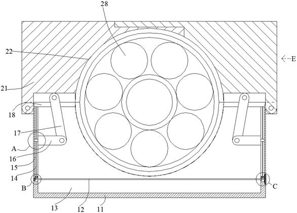
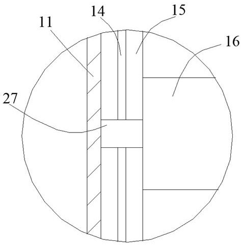
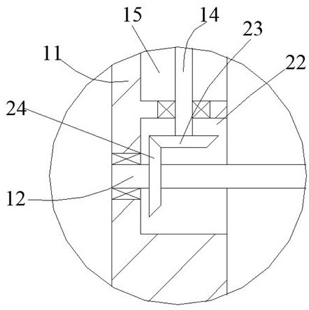
[0025] Such as Figure 1-Figure 7 As shown, the present invention is described in detail. For the convenience of description, the orientations mentioned below are now stipulated as follows: figure 1 The up, down, left, right, front and back directions of the projection relationship are the same. A turning-milling compound machine tool of the present invention includes a box body 11. The box body 11 is provided with a cavity 13, and the two sides of the box body 11 are rotated. The clamping block 21, the clamping block 21 and the box body 11 are provided with a matching ring 22, the clamping between the coupling rings 22 is provided with a matching bearing 28, and the cavity 13 is provided with a clamping block 21 Open and close to indirectly make the matching ring 22 close and clamp the matching bearing 28, and the front and rear sides of the matching ring 22 and the box body 11 are provided with parts for matching with the matching bearing 28 to offset each other. A closed c...


PUM


Abstract

The invention discloses a turning and milling composite machine tool which comprises a box body. A containing cavity is formed in the box body, symmetrical clamping blocks are rotatably arranged on the two sides of the box body, cooperation rings are arranged in the clamping blocks and the box body, and a cooperation bearing is arranged between the cooperation rings in a clamped manner. A swing clamping device enabling the clamping blocks to be opened and closed so as to indirectly enable the cooperation rings to seal and clamp the cooperation bearing is arranged in the containing cavity, andsealing and abutting devices used for abutting against parts cooperating with the cooperation bearing so as to prevent sundries from entering the cooperation bearing are arranged on the front side andthe rear side of the cooperation ring and the front side and the rear side of the box body. According to the turning and milling composite machine tool, the cooperation bearing can be rapidly replaced and clamped, and sufficient abutting can be achieved on shaft parts in cooperation connection with the cooperation bearing so as to prevent sundries from entering the turning and milling composite machine tool.

Description

technical field [0001] The invention relates to the technical field of machine tool supporting equipment, in particular to a turning-milling compound machine tool. Background technique [0002] The most common part of the existing turning-milling machine tool should be the bearing, but the existing turning-milling machine tool often needs to use the motor to drive the threaded shaft to rotate, and then the threaded shaft needs to be installed on the bearing, because the bearing and the threaded shaft When rotating, if the corresponding supporting bearings are not well lubricated and maintained, the damaged bearings are replaced in time and the parts debris and dust in the external space are prevented from invading, resulting in wear and abnormal operation of the bearings, making the equipment The accuracy is reduced, and the actual working efficiency of the bearing and the corresponding threaded shaft is also reduced. Due to the existence of the above shortcomings, the machi...

Claims


Application Information

Patent Timeline
IPC IPC(8): B23Q11/00B23Q11/08
CPCB23Q11/00B23Q11/08
Inventor 王涛
Owner 王涛
Why Eureka
Try Eureka