
Yarn end-forming device of yarn reeling machine

A technology of a spinning device and a spinning machine, which is applied in the directions of transportation and packaging, transportation of filamentous materials, and processing of thin materials, can solve the problems of device structure and other problems.

Pending Publication Date: 2021-03-16
TIANJIN POLYTECHNIC UNIV
View PDF0 Cites 2 Cited by
  • Summary
  • Abstract
  • Description
  • Claims
  • Application Information

AI Technical Summary

Problems solved by technology

The utility model patent "Yarn Automatic Threading Device Applied to Shaking Machine" (application number 2019204913958) discloses a threading device, but the structure of the device is relatively complicated.

Method used


Image

  • Yarn end-forming device of yarn reeling machine
  • Yarn end-forming device of yarn reeling machine

Examples


Embodiment Construction

[0019] The following is a specific embodiment of a spin-in device for a spinning machine of the present invention in conjunction with the illustrations. The embodiment is only an illustration of the present invention and does not constitute a limitation to the claims of the present invention. The unmentioned parts of the present invention are applicable to the present invention have technology.

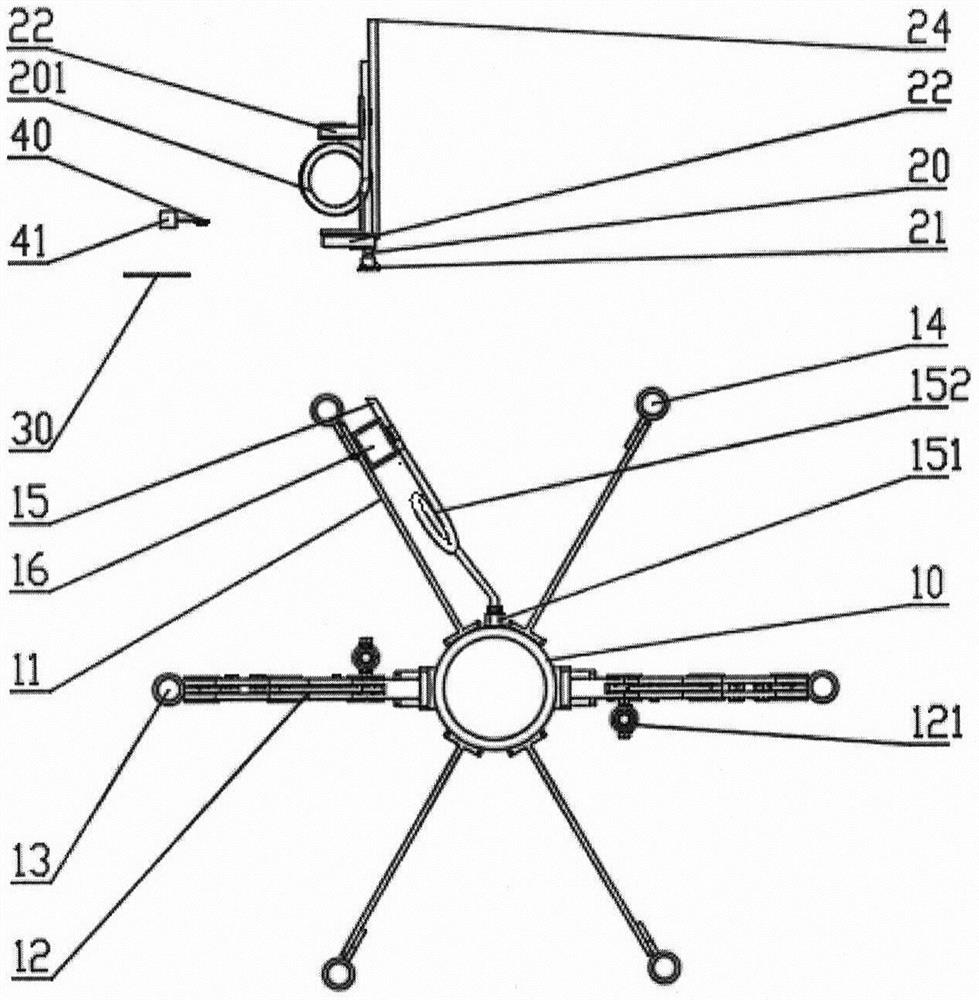
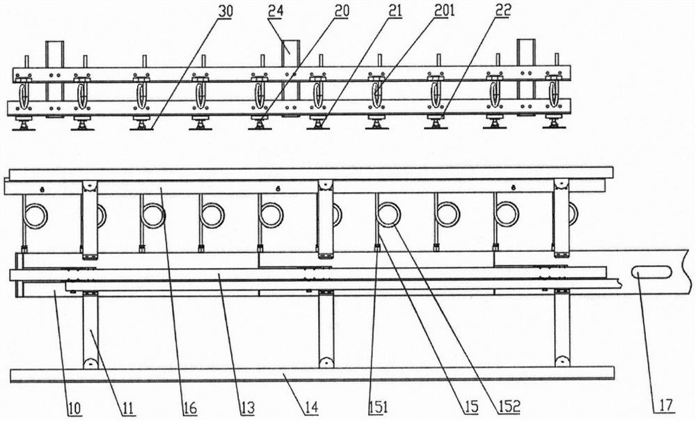
[0020] A kind of embodiment of spinning machine spinning-in device of the present invention (such as Figure 1-2 shown):

[0021] The yarn frame shaft 10 of the spinning machine in this embodiment is a hollow shaft, and is a sealed structure except for the yarn frame suction port 17 and the air nozzle 151 opened on the shaft. The yarn frame suction port 17 is a hole opened outside the yarn frame shaft 10 for connecting Negative pressure suction device, for example, adopts a rubber negative pressure interface piece similar in shape to the yarn frame suction port 17 to introduce negati...


PUM


Abstract

The invention relates to the end-forming technology of a yarn reeling machine during yarn reeling, and particularly relates to a yarn end-forming device of the yarn reeling machine. The yarn end-forming device is used on the yarn reeling machine and comprises a yarn moving device and an end-forming holding device, wherein the yarn moving device comprises a yarn moving component, a yarn moving holding component and a yarn moving sensor; the end-forming holding device comprises an end-forming yarn sucking component and an end-forming holding component which are arranged on a yarn frame; the yarnmoving component and the end-forming yarn sucking component are components which can suck yarn ends into the yarn moving component and the end-forming yarn sucking component by using air flow and areprovided with through holes; one end of each through hole is open, and the other end of each through hole is connected to a negative pressure air suction device; the yarn moving holding component andthe end-forming holding component are components for applying tension to yarns sucked by the yarn moving component and the end-forming yarn sucking component; the yarn moving sensor is a device for detecting whether yarns exist at the mounting position of the yarn moving sensor in the yarn moving component; and the end-forming yarn sucking component and a yarn frame shaft are kept relatively static. The yarn end-forming device of the yarn reeling machine has a simple structure; and by using the technology, the automation of yarn reeling and leasing is convenient to realize.

Description

technical field [0001] The present invention relates to the spinning-in technology of yarn reeling machine, in particular to a spinning-in device of yarn reeling machine, which is used on the yarn reeling machine, and comprises a yarn-moving device and a spinning-in holding device, and the yarn-moving device It includes a yarn moving part, a yarn moving holding part and a yarn moving sensor. The spinning-in holding device includes a spinning-in suction part and a spinning-in holding part installed on the The yarn component is a component with a through hole that can suck the yarn end into it by airflow. One end of the through hole is open, and the other end is connected to the negative pressure suction device. Yarn component and yarn suction component for applying tension to the yarn sucked in. The yarn moving sensor is a device that detects whether there is yarn at the installation position of the yarn moving sensor inside the yarn moving component. The yarn spinning componen...

Claims


Application Information

Patent Timeline
IPC IPC(8): B65H67/08B65H51/16B65H57/06
CPCB65H51/16B65H57/06B65H67/081B65H2701/31
Inventor 吕汉明陈祥燕辛胜利
Owner TIANJIN POLYTECHNIC UNIV
Learn More