
A method for real-time prediction of the risk of tower sweeping when blades pass through the tower

A real-time prediction and blade technology, which is applied in the control of wind turbines, the monitoring of wind turbines, the configuration of installation/supporting wind turbines, etc., can solve the problem of increased cost of wind turbines, lasers are easily affected by the external environment, measurement distance and measurement accuracy Reduce problems such as easy installation and maintenance, avoid tower sweeping accidents, and improve reliability

Active Publication Date: 2022-04-01
东方电气风电股份有限公司
View PDF15 Cites 0 Cited by
  • Summary
  • Abstract
  • Description
  • Claims
  • Application Information

AI Technical Summary

Problems solved by technology

The disadvantage of this method is that the blade rotation plane will change with the wind direction, which means that multiple radar probes need to be arranged on the outer surface of the tower at the same height, resulting in an increase in the cost of the wind turbine
The disadvantage of this method is that the vision of the camera is susceptible to interference
All of the above reduce the reliability of camera-based measurement methods
[0006] The third category is the measurement method based on laser ranging. The disadvantage of this method is that the laser is easily affected by the external environment, which reduces the measurement distance and measurement accuracy. At the same time, the closest distance between the blade and the tower surface is not the fixed section of the blade. If multiple laser ranging devices are used, the cost will increase significantly

Method used

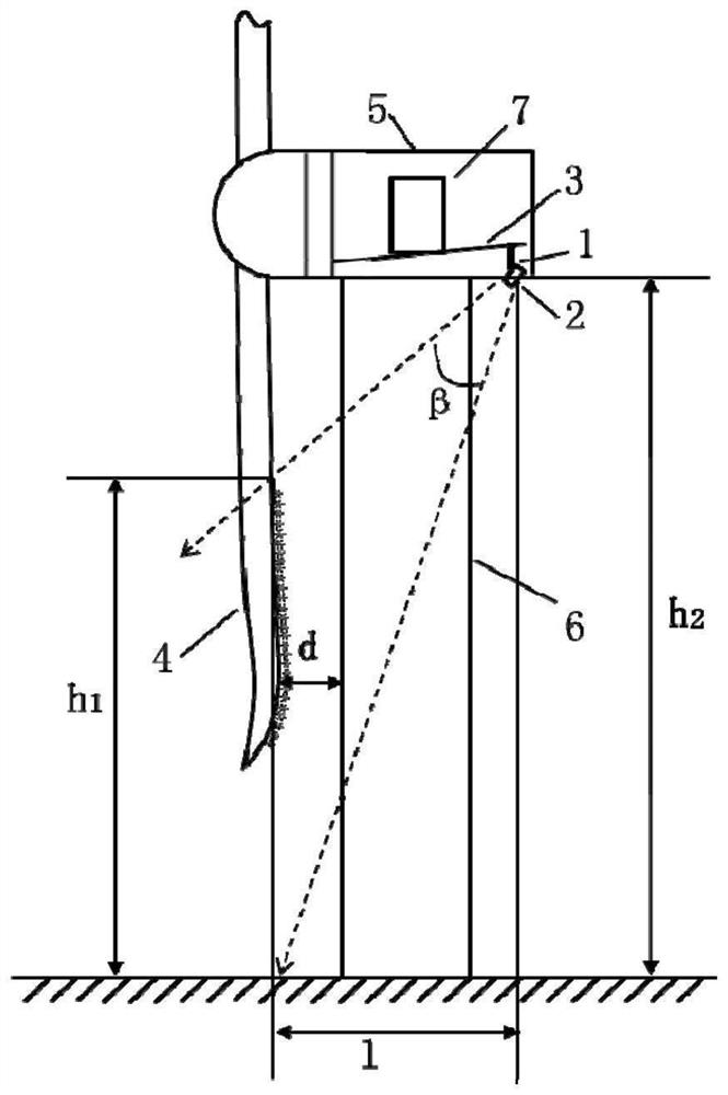
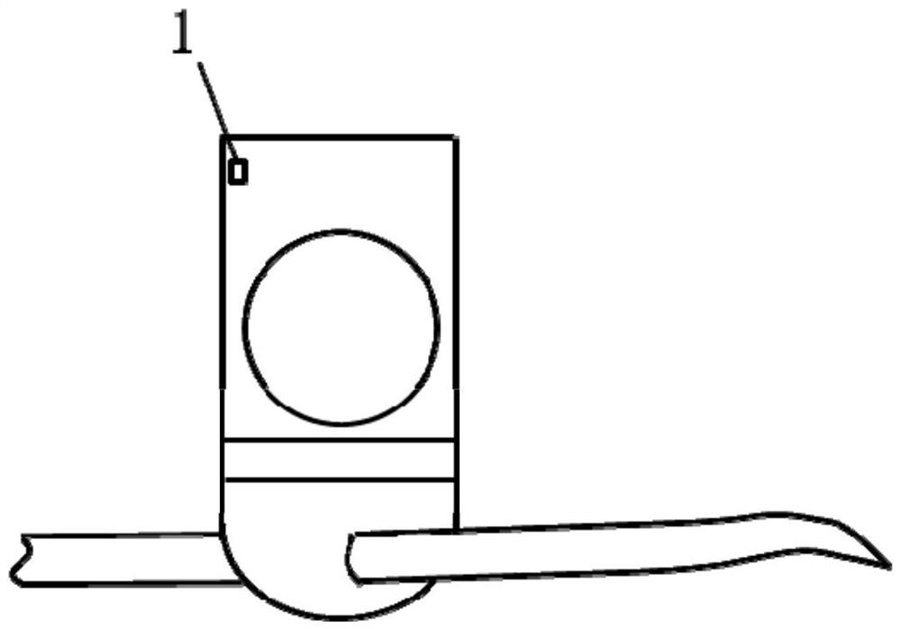
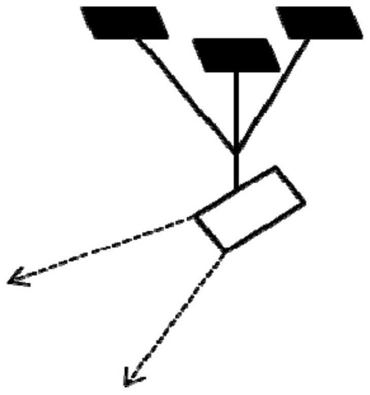

Image

  • A method for real-time prediction of the risk of tower sweeping when blades pass through the tower
  • A method for real-time prediction of the risk of tower sweeping when blades pass through the tower
  • A method for real-time prediction of the risk of tower sweeping when blades pass through the tower

Examples


Embodiment Construction

[0043] In order to clearly illustrate the specific implementation manners of the present invention, the exemplary embodiments of the present invention will now be described in detail in conjunction with the accompanying drawings.

[0044] The invention provides a method for real-time prediction of tower sweep risk when blades pass through the tower, the method comprising the following steps:

[0045] In the first step, the millimeter-wave radar is installed at a preset position at the tail of the wind turbine nacelle, and the normal of the millimeter-wave radar is adjusted so that the beam of the millimeter-wave radar can illuminate a designated area within the blade rotation plane. The preset position is the outer side of the lower surface of the tail of the nacelle, and the designated area is the tip prebend part of the blade.

[0046] refer to figure 1In this exemplary embodiment, the millimeter-wave radar 2 is fixedly connected to the nacelle frame 3 by using the bracket ...


PUM


Abstract

The invention discloses a method for real-time prediction of the risk of tower sweeping when blades pass through the tower. By installing a millimeter-wave radar at a preset position at the tail of the wind turbine nacelle, reliable measurement information is collected and a clearance model of the wind turbine tower is established; using millimeter-wave The radar detects the overall blade passing through the designated area in the rotation plane of the wind rotor to obtain the spatial position and deformation velocity information of the target point when the blade passes through the designated area in the rotation plane of the wind rotor, and calculates the clearance value at each target point and each target point The amount of deformation when passing through the tower, and assess the risk of blade sweeping the tower, and make different control actions according to the risk level. The invention can predict the tower-sweeping risk when the blades pass through the tower for a certain time in advance, and simultaneously monitor the clearance values ​​of multiple target points and the deformation when passing through the tower, thereby improving the reliability and safety of the system.

Description

technical field [0001] The invention relates to the technical field of wind power, in particular to a method for real-time prediction of tower sweep risk when blades pass through a tower. Background technique [0002] In the field of wind power technology, the tower headroom refers to the minimum distance between the blade surface and the tower surface. During the operation of the unit, the increase of wind speed will make the tip of the blade close to the surface of the tower, and in severe cases, it may cause the blade to sweep the tower and directly cause economic losses. Based on the real-time measurement value and threshold judgment results of the tower clearance, on the one hand, it can avoid blade sweeping accidents and improve the safety of wind turbines; on the other hand, it has guiding significance for blade weight reduction, which can reduce the manufacturing and maintenance of wind turbines cost. [0003] At present, the existing measurement methods for measur...

Claims


Application Information

Patent Timeline
Patent Type & Authority Patents(China)
IPC IPC(8): F03D17/00F03D7/02F03D13/20
CPCF03D17/00F03D7/02F03D13/20Y02E10/72Y02E10/728Y02B10/30
Inventor 兰杰郑大周王其君姚森彭先伟李颖林淑尹景勋
Owner 东方电气风电股份有限公司
Learn More