Connected structure configuration assembly

A technology for configuring components and connecting structures, applied in fixtures, mechanical equipment, etc., can solve the problems of consuming manpower, material resources, time and financial resources, increasing manufacturing costs and production costs, and increasing the labor intensity of operators, so as to achieve no potential safety hazards. , the effect of saving raw materials, strong scalability and compatibility

Pending Publication Date: 2021-03-16
闫新 +1
View PDF0 Cites 0 Cited by
  • Summary
  • Abstract
  • Description
  • Claims
  • Application Information

AI Technical Summary

Problems solved by technology

The existing connectors obviously cannot realize the structural connection, and it is very troublesome when the connection port of the object is changed or replaced, which takes time and effort, increases the labor intensity of the operator, greatly increases the production cost and production cost, and works inefficiently For the objects connected to the building, it may be necessary to replace or modify the original pre-buried connectors on the building, which is more troublesome, time-consuming and labor-intensive. If it is a place where facilities, equipment and various connecting objects are frequently replaced or displaced, It consumes more manpower, material resources, time and financial resources

Method used


Image

  • Connected structure configuration assembly
  • Connected structure configuration assembly
  • Connected structure configuration assembly

Examples


Embodiment 1

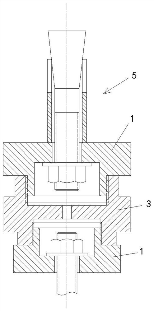
[0046] Such as figure 1 Shown: the configuration assembly of the connection structure of the present invention, including the intermediate connecting piece 3 and the female connecting piece 1 .

[0047] Such as Figure 9 , 10 As shown: one end of the intermediate connector 3 has a first thread 31 of the intermediate connector, and the other end has a second thread 32 of the intermediate connector.

[0048] Such as Figure 5 , 6 Shown: there is a through hole 11 on one end of the hole connector 1, and a hole connector thread 13 and an open cavity 12 matched with the first thread 31 of the intermediate connector on the other end, the through hole 11 and the cavity 12 connected. The hole connector 1 and the intermediate connector 3 are screwed together through the first thread 31 of the intermediate connector and the thread 13 of the hole connector. The open cavity 12 means that one end of the cavity part communicates with the through hole 11, and the other end is open (see...

Embodiment 2

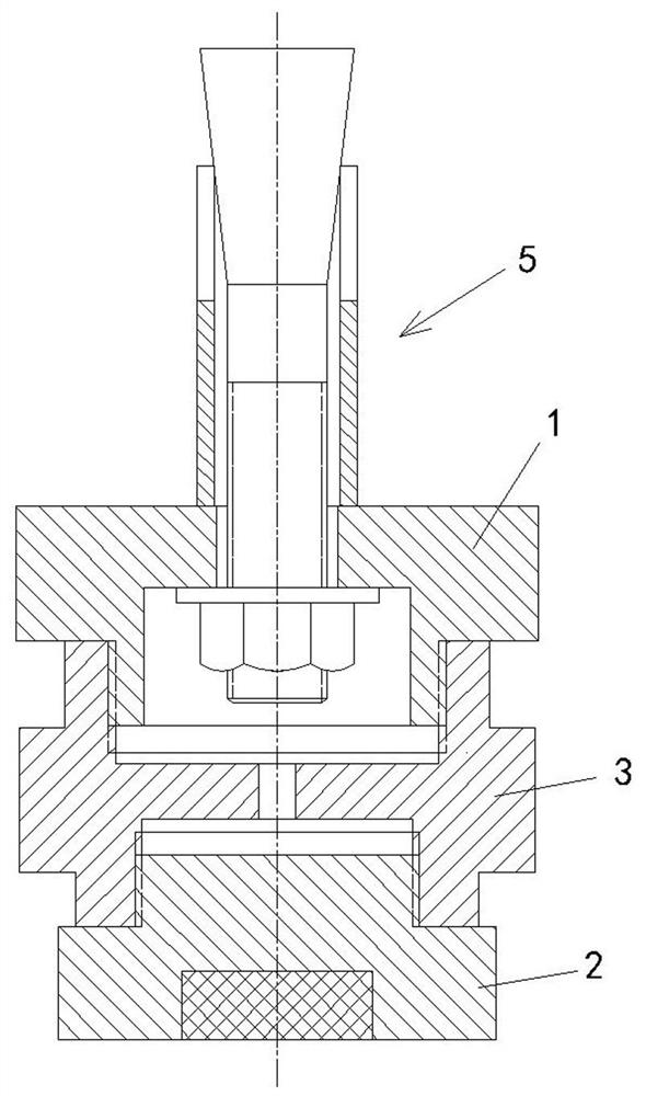
[0058] Such as figure 2 , 7 , Shown in 8: the difference with embodiment 1 is that the second thread 32 of the intermediate connector on the intermediate connector 3 is threadedly connected with the magnetic connector 2, and the magnetic connector thread 22 is connected with the intermediate connector thread 2 on the magnetic connector 2. The second thread 32 of the connector matches. After tightening, the magnetic connector resting platform 21 on the magnetic connector 2 abuts against the end of the intermediate connector 3 . The magnetic connector 2 is fixedly embedded with a permanent magnet 23 , and the end of the magnetic connector 2 has a magnetic connector suction contact surface 24 . That is, one end of the intermediate connector 3 is screwed to the hole connector 1 , and the other end is screwed to the magnetic connector 2 . The magnetic connector 2 is a series of products like the intermediate connector 3 and has various specifications and sizes.

Embodiment 3

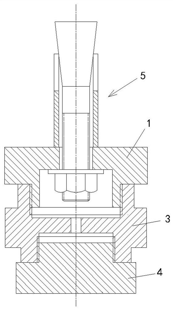
[0060] Such as image 3 , 11 , shown in 12: the difference from embodiment 1 is that the second thread 32 of the intermediate connector on the intermediate connector 3 is threadedly connected with the magnetically friendly connector 4 that can be attracted by the permanent magnet (NdFeB). The connecting piece 4 is made of a magnetophilic material and can be magnetically attracted. The magnetically friendly connecting piece 4 has a magnetically friendly connecting piece thread 43 matching with the second thread 32 of the intermediate connecting piece. After fastening, the magnetic-friendly connecting member resting platform 42 on the magnetic-friendly connecting member 4 abuts against the end of the intermediate connecting member 3 . The end of the magnetic-friendly connector 4 has a magnetic connector suction contact surface 41 . That is, one end of the intermediate connector 3 is screwed to the hole connector 1 , and the other end is screwed to the magnetic connector 4 . ...


PUM


Abstract

The invention relates to a connected structure configuration assembly. The connected structure configuration assembly is characterized in that one end of a middle connecting piece is provided with a first thread of the middle connecting piece, and the other end of the middle connecting piece is provided with a second thread of the middle connecting piece; a through hole is formed in one end of a hole type connecting piece; a hole type connecting piece thread matched with the first thread of the middle connecting piece and an open type cavity are formed in the other end of the hole type connecting piece; the through hole is communicated with the cavity; the middle connecting piece is in threaded connection with the hole type connecting piece or a magnetic type connecting piece or a magnetophilic connecting piece through the second thread of the middle connecting piece; a magnetic block is embedded in the magnetic connecting piece; the end of the magnetic connecting piece is provided with a magnetic connecting piece attraction contact surface; the end of the magnetophilic connecting piece is provided with a magnetophilic connecting piece attraction contact surface; the middle connecting piece, the hole type connecting piece, the magnetic type connecting piece and the magnetophilic connecting piece are all series products; and the series products refer to various specifications and sizes of all the parts. The assembly can realize connection structuralization.

Description

technical field [0001] The invention relates to a connection assembly, in particular to a structured arrangement for detachable connection. Background technique [0002] Connectors are widely used. For example, the installation of various indoor and outdoor facilities and equipment requires connectors to be fixedly connected, including various production equipment and devices in the factory workshop, various indoor lighting devices, indoor and outdoor public Places are used to indicate and guide objects, video, audio equipment, advertising devices, various display devices, various special facilities installed indoors and outdoors in various industries, equipment, various appliances, squares in cities, roadsides , Various devices set up on the building, etc. At present, most of the connectors used for installing the above-mentioned various devices are bolt connectors, and the connection method is to use the bolt connectors adapted to the connection ports of the two connected...

Claims


Application Information

Patent Timeline
Patent Type & Authority Applications(China)
IPC IPC(8): F16B1/00
CPCF16B1/00F16B2200/83
Inventor 闫新陈岩
Owner 闫新
Why Eureka
Try Eureka