Magnetic connection structured configuration assembly with self-protection function

A technology for connecting structures and configuring components, which is applied in the direction of fixtures and mechanical equipment, can solve the problems of consuming manpower, material resources, time and financial resources, increasing production costs and production costs, and increasing the labor intensity of operators, so as to reduce operating costs. , saving raw materials, powerful expansion and compatibility effects

Pending Publication Date: 2021-03-16
闫新 +1
View PDF0 Cites 0 Cited by
  • Summary
  • Abstract
  • Description
  • Claims
  • Application Information

AI Technical Summary

Problems solved by technology

The existing connectors obviously cannot realize the structural connection, and it is very troublesome when the connection port of the object is changed or replaced, which takes time and effort, increases the labor intensity of the operator, greatly increases the production cost and production cost, and works inefficiently For the objects connected to the building, it may be necessary to replace or modify the original pre-buried connectors on the building, which is more troublesome, time-consuming and labor-intensive. If it is a place where facilities, equipment and various connecting objects are frequently replaced or displaced, It consumes more manpower, material resources, time and financial resources

Method used


Image

  • Magnetic connection structured configuration assembly with self-protection function
  • Magnetic connection structured configuration assembly with self-protection function
  • Magnetic connection structured configuration assembly with self-protection function

Examples


Embodiment Construction

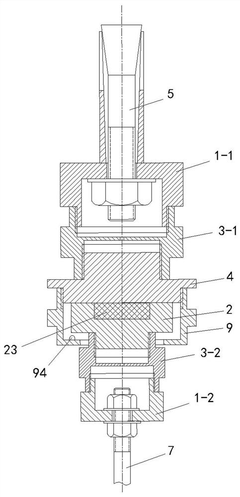
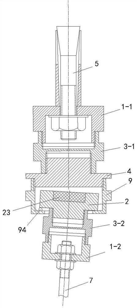
[0047] Such as figure 1 Shown: the self-protection magnetic connection structural configuration assembly of the present invention includes a first intermediate connecting piece 3-1, a second intermediate connecting piece 3-2, a first hole connecting piece 1-1, a second intermediate connecting piece 3-1, Two-hole connectors 1-2, magnetic connectors 2, magnetic-friendly connectors 4, and protective sleeves 9.

[0048] The first intermediate connector 3-1 has the same structure as the second intermediate connector 3-2, as image 3 , 4 As shown: one end of the first intermediate connector 3-1 has the first thread 31 of the intermediate connector, and the other end has the second thread 32 of the intermediate connector. Since the two pieces have the same structure, the second intermediate connector 3 will not be described again. -2 structure.

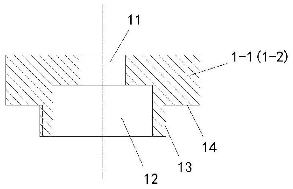
[0049] The first hole connector 1-1 has the same structure as the second hole connector 1-2, such as Figure 7 , 8 Shown: there is a t...


PUM


Abstract

The invention discloses a magnetic connection structured configuration assembly with a self-protection function. The magnetic connection structured configuration assembly with the self-protection function comprises a first middle connecting piece, a second middle connecting piece, a first hole type connecting piece, a second hole type connecting piece, a magnetic connecting piece, a magnetophilicconnecting piece and a protective sleeve. The first hole type connecting piece and the first middle connecting piece are in threaded connection, the first middle connecting piece and the magnetophilicconnecting piece are in threaded connection, the second hole type connecting piece and the second middle connecting piece are in threaded connection, and the second middle connecting piece and the magnetic connecting piece are in threaded connection. The magnetic connecting piece and the magnetophilic connecting piece are connected with each other in an attracting manner; The protective sleeve isin threaded connection with the magnetophilic connecting piece through connecting threads and protective threads. The magnetophilic connecting piece is located in an inner cavity of the protective sleeve, and an inner table of the protective sleeve covers the outer side of a leaning table of the magnetic connecting piece. All the connecting pieces are series products. The magnetic connection structured configuration assembly with the self-protection function has the advantages of being simple in structure, saving time and labor, improving working efficiency, lowering labor intensity of operators, reducing cost and being flexible to change.

Description

technical field [0001] The invention relates to a connection assembly, in particular to a detachable magnetic connection structural configuration assembly with self-protection function. Background technique [0002] Connectors are widely used. For example, the installation of various indoor and outdoor facilities and equipment requires connectors to be fixedly connected, including various production equipment and devices in the factory workshop, various indoor lighting devices, indoor and outdoor public Places are used to indicate and guide objects, video, audio equipment, advertising devices, various display devices, various special facilities installed indoors and outdoors in various industries, equipment, various appliances, squares in cities, roadsides , Various devices set up on the building, etc. At present, most of the connectors used for installing the above-mentioned various devices are bolt connectors, and the connection method is to use the bolt connectors adapte...

Claims


Application Information

Patent Timeline
Patent Type & Authority Applications(China)
IPC IPC(8): F16B1/00
CPCF16B1/00F16B2200/83
Inventor 闫新陈岩
Owner 闫新
Why Eureka
Try Eureka