
Protective shell of microgrid energy storage device

A technology for protecting shells and energy storage devices. It is applied in the direction of electric energy storage systems, electrical equipment shells/cabinets/drawers, and power electronics modification. It can solve the problem of reducing the use efficiency and effect of energy storage devices and affecting microgrid energy storage. Problems such as safety in use of the device, burnout of internal components of the energy storage device, etc., to achieve the effect of improving the efficiency and effect of use, improving stability and reliability, and simple structure

Pending Publication Date: 2021-03-16
戴彦文
View PDF5 Cites 0 Cited by
  • Summary
  • Abstract
  • Description
  • Claims
  • Application Information

AI Technical Summary

Problems solved by technology

[0004] The purpose of the present invention is to solve the above problems by designing a protective shell for a micro-grid energy storage device, which solves the problem that the existing micro-grid energy storage device will generate a certain amount of heat when it is used for a long time. When the micro-grid energy storage devices are used at the same time, the temperature inside the energy storage device will rise rapidly, which will easily burn out the internal components of the energy storage device, reduce the service life of the energy storage device, and seriously affect the micro-grid. The use of the energy storage device is safe and inconvenient to use, which reduces the efficiency and effect of the energy storage device

Method used


Image

  • Protective shell of microgrid energy storage device
  • Protective shell of microgrid energy storage device
  • Protective shell of microgrid energy storage device

Examples


Embodiment

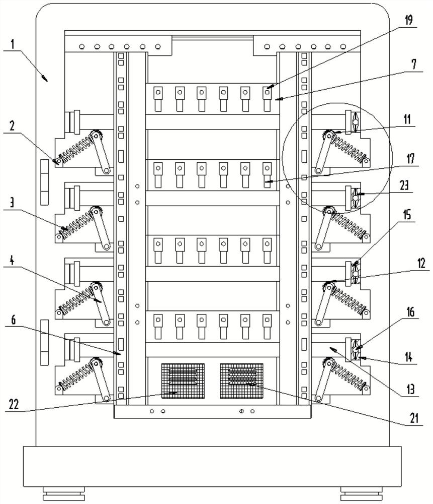
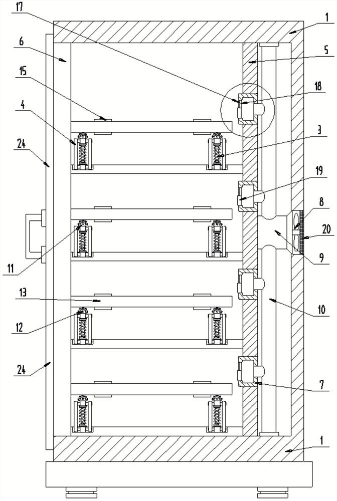
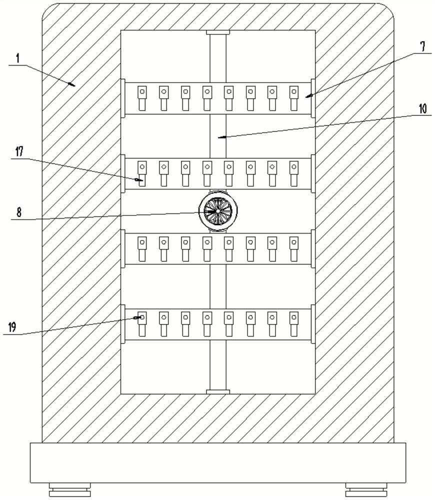
[0029] Embodiment: A protective shell of a micro-grid energy storage device, including a protective shell 1, and an anti-shock structure and a heat dissipation structure are installed inside the protection;

[0030] see Figure 1-5 , in the specific implementation process, the anti-vibration structure includes: several hinge seats 2, several springs 3, several rotating frames 4 and anti-vibration parts; the connection relationship is as follows:

[0031] Several hinge seats 2 are respectively fixed inside the protective shell 1, several springs 3 are movably arranged on several hinge seats 2, and one ends of several swivel frames 4 are respectively movably arranged in the protective shell 1. inside, and the other end is movably arranged on the other end of several first springs 3, and the anti-vibration part is arranged on the upper ends of several first springs 3 and the rotating frame 4 respectively.

[0032] In the specific implementation process, it should be noted that t...


PUM


Abstract

The invention discloses a protective shell of a microgrid energy storage device. The protective shell comprises a protective shell body, wherein a shockproof structure and a heat dissipation structureare mounted in the protective shell body; and the shockproof structure comprises a plurality of hinged supports, a plurality of springs, a plurality of rotating frames and shockproof parts, the multiple hinged supports are fixed in the protective shell body, the multiple springs are movably arranged on the multiple hinged supports, and one ends of the multiple rotating frames are movably arrangedin the protective shell body. The protective shell has the beneficial effects that the protective shell is simple in structure, reasonable in design, simple in overall structure, convenient to operate and use; and with the protective shell, the purpose of heat dissipation of the microgrid energy storage device is achieved, the service life of the energy storage device is prolonged, the use efficiency and use effect of the energy storage device are improved, a mounting plate in the shell is protected, damping effect on the mounting plate is achieved, and the stability and reliability of the micro-grid energy storage device on the mounting plate are improved, shockproof performance is improved, and service life is prolonged.

Description

technical field [0001] The invention relates to the technical field of micro-grid energy storage devices, in particular to a protective shell of a micro-grid energy storage device. Background technique [0002] Microgrid, also translated as microgrid, refers to a small power generation and distribution system composed of distributed power sources, energy storage devices, energy conversion devices, loads, monitoring and protection devices, etc. The proposal of microgrid aims to realize the flexible and efficient application of distributed power, and solve the problem of grid connection of distributed power with a large number and various forms. The development and extension of microgrids can fully promote the large-scale access of distributed power sources and renewable energy, and realize the highly reliable supply of various energy forms for loads. Smart grid transition. [0003] The microgrid needs to store a huge amount of electric energy in the process of use, so it is...

Claims


Application Information

Patent Timeline
Patent Type & Authority Applications(China)
IPC IPC(8): H05K5/02H05K7/20H02J15/00F16F15/02F16F15/04F16F15/067
CPCH05K5/0217H05K7/20136H05K7/20909H05K5/0213H02J15/00F16F15/02F16F15/067F16F15/04F16F15/021
Inventor 戴彦文
Owner 戴彦文
Learn More