
Recycling device for clearing waste paint bucket

A recycling device and paint bucket technology, applied in paint-related fields, can solve the problems of skin corrosion on the hands of recycling personnel, threats to the physical and mental health of recycling personnel, and time-consuming and laborious paint cleaning, so as to protect the surrounding environment, promote economic growth, and reduce human and material resources. Effect

Inactive Publication Date: 2021-03-19
TIANJIN XIANJUN CRAFTS CO LTD
View PDF0 Cites 2 Cited by
  • Summary
  • Abstract
  • Description
  • Claims
  • Application Information

AI Technical Summary

Problems solved by technology

[0002] Paint bucket refers to a container for holding paint, generally made of white iron, with a layer of anti-rust packaging paint on the surface; after whitewashing and decoration of the wall, there will often be a certain amount of paint left in the paint bucket. The paint in the barrel will continue to harden. When the paint barrel is recycled, if the paint in the barrel is not completely cleaned, it is easy to corrode the skin of the hands of the recycler during recycling, and the waste paint will emit toxic substances, which is easy It will cause serious harm to the nervous system of the recyclers, thereby threatening the physical and mental health of the recyclers; and the cleaning of hardened paint is time-consuming and laborious, and the efficiency of manual cleaning is not high, which will increase the cost of recycling. The recovery device for cleaning up waste paint buckets can solve the above problems

Method used


Image

  • Recycling device for clearing waste paint bucket
  • Recycling device for clearing waste paint bucket
  • Recycling device for clearing waste paint bucket

Examples


Embodiment Construction

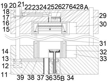
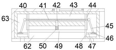
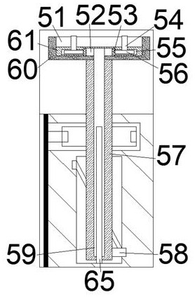
[0015] Combine below Figure 1-3 The present invention is described in detail, wherein, for the convenience of description, the orientations mentioned below are stipulated as follows: figure 1 The up, down, left, right, front and back directions of the projection relationship itself are the same.

[0016] A recovery device for cleaning waste paint buckets according to the present invention includes a box body 11, a lower rotating cavity 33 with an opening facing upwards is provided inside the box body 11, and the lower part of the lower rotating cavity 33 is connected to a There is a waste chamber 36 with an opening facing downwards, the lower side of the lower rotating chamber 33 is provided with a synchronous chamber 39 partially communicated with the waste chamber 36, and the lower side of the synchronous chamber 39 is provided with a right side of the waste chamber 36 Lifting chamber 35, a cleaning device is provided in the lower rotating chamber 33, and the cleaning devi...


PUM


Abstract

The invention discloses a recycling device for clearing a waste paint bucket. The recycling device comprises a box body, wherein a lower rotating cavity with an upward opening is formed in the box body, a waste cavity with a downward opening is formed in the lower side of the lower rotating cavity in a partial communicating mode, a synchronous cavity which partially communicates with the waste cavity is formed in the lower side of the lower rotating cavity, a lifting cavity located at the right side of the waste cavity is formed in the lower side of the synchronous cavity, a clearing device isarranged in the lower rotating cavity, and the clearing device comprises a transmission shaft which is rotationally arranged on the upper end wall of the lifting cavity, penetrates through the synchronous cavity and extends into the lower rotating cavity. According to the recycling device, the paint bucket is clamped and fixed, paint which is hardened inside is crushed, and paint adhering to theinner wall of the paint bucket is cleared, so that the paint bucket recycling quality is improved, manpower and material resources consumed for clearing the waste paint are reduced, the recycling efficiency is improved, economic growth is promoted, and the waste paint can be treated in a centralized mode.

Description

technical field [0001] The invention relates to the related field of paint, in particular to a recovery device for cleaning waste paint barrels. Background technique [0002] Paint bucket refers to a container for holding paint, generally made of white iron, with a layer of anti-rust packaging paint on the surface; after whitewashing and decoration of the wall, there will often be a certain amount of paint left in the paint bucket. The paint in the barrel will continue to harden. When the paint barrel is recycled, if the paint in the barrel is not completely cleaned, it is easy to corrode the skin of the hands of the recycler during recycling, and the waste paint will emit toxic substances, which is easy It will cause serious harm to the nervous system of the recyclers, thereby threatening the physical and mental health of the recyclers; and the cleaning of hardened paint is time-consuming and laborious, and the efficiency of manual cleaning is not high, which will increase ...

Claims


Application Information

Patent Timeline
Patent Type & Authority Applications(China)
IPC IPC(8): B08B9/38B08B13/00
CPCB08B9/38B08B13/00
Inventor 周习宇
Owner TIANJIN XIANJUN CRAFTS CO LTD
Learn More