Supercharge Your Innovation With Domain-Expert AI Agents!

Measurement gauge combination and using method thereof

A technology for checking fixtures and locking screws, which is used in manufacturing tools, measuring/indicating equipment, metal processing equipment, etc., and can solve the problems of deviation from the center of rotation, deviation of the second guide block from the original design position, and out of tolerance of the workpiece.

Active Publication Date: 2021-03-19
福建省威诺数控有限公司
View PDF6 Cites 0 Cited by
  • Summary
  • Abstract
  • Description
  • Claims
  • Application Information

AI Technical Summary

Problems solved by technology

[0004] Since the first guide block takes into account the two functions of positioning and guiding, after using the parallel inspection tool to align the two sides of the 461mm size and the 461mm size in parallel, the alignment of the fixed range surface is completed, but at this time the guiding surface of the first guiding block is on the fixture The position of the guide block has not been fixed. If the piece is pinned and fixed, when the guide surface of the fixture is adjusted with a size inspection tool, the guide surface of the second guide block will obey the straight line direction of the guide surface of the first guide block, which will cause the position of the second guide block to deviated from the original design position
In this way, when the spindle box is clamped, it will be placed incorrectly or deviated from the center of rotation, which will cause serious consequences for the workpiece to be processed.

Method used


Image

  • Measurement gauge combination and using method thereof
  • Measurement gauge combination and using method thereof
  • Measurement gauge combination and using method thereof

Examples


Embodiment 1

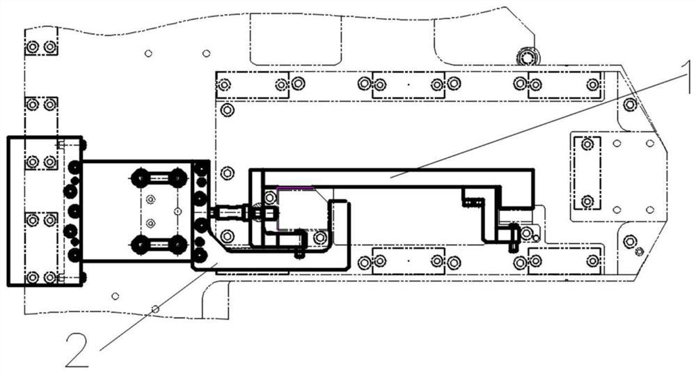
[0053] Such as figure 1 As shown, a combination of measuring and checking tools includes a size checking tool 1 and a parallel checking tool 2. The abutment bolt and the support nail 113 are arranged coaxially, and the abutting position of the abutment bolt contacts the first positioning block 111 .

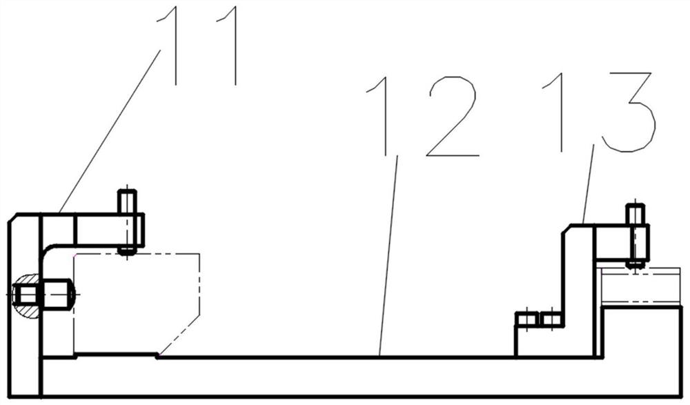
[0054] Such as figure 2 As shown, the dimension inspection tool 1 includes a positioning part 11 , an alignment part 12 and a locking part 13 , and the positioning part 11 and the locking part 13 are respectively provided at both ends of the alignment part 12 .

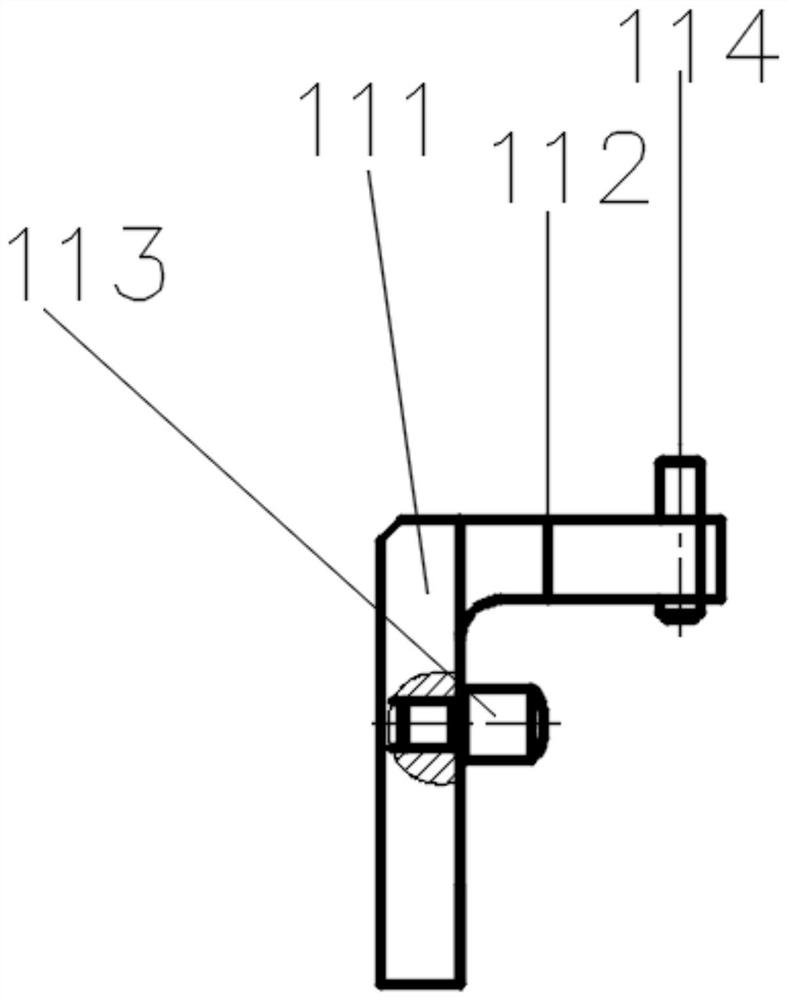
[0055] Such as image 3 As shown, the positioning part 11 includes a first positioning block 111, a second positioning block 112, a supporting nail 113 and a first locking screw 114, one end of the first positioning block 111 is vertically connected with one end of the second positioning block 112, and the first positioning part 11 The other end is vertically connected to the alignment part 12, the first positioning ...


PUM


Abstract

The invention discloses a measurement gauge combination and a using method thereof. The using method comprises the following steps of: placing a parallelism gauge on a clamp body; prelocking a connecting part of the parallelism gauge on the clamp body; placing a size gauge on a clamp heightening base, enabling a first alignment part to be close to a first guide block, enabling a second alignment part to be close to a second guide block, enabling a first locking screw to be abutted against the face opposite to the guide face of the first guide block, and enabling a second locking screw to be abutted against the face opposite to the guide face of the second guide block without complete abut-against; a third locking screw of the parallelism gauge is abutted against the side surface of a clamppositioning block to deadlock a bolt connection screw; screwing down a press-against screw to eliminate a gap between two measurement gauges, and enabling the arc surface of a supporting nail to be leaned against the fixed-stroke surface; enabling a size gauge and the locking screw to be deadlocked; and deadlocking two aligned guide block screws and beating a positioning pin. Through the combineduse of the two sets of gauges, control on the parallelism and the sizes of the clamp alignment surface and the fixed-stroke surface which are different in height and the perpendicularity between theclamp alignment surface and the two guide surfaces is implemented when a clamp is assembled and debugged, and the parallelism and the sizes of the two guide surfaces are guaranteed.

Description

technical field [0001] The invention relates to the field of inspection tools for machine tools, in particular to a combination of inspection tools. Background technique [0002] The spindle box is an important part of the machine tool, which is used to arrange the working spindle of the machine tool and its transmission parts and corresponding additional mechanisms. The headstock is a complex transmission part, including the main shaft assembly, reversing mechanism, transmission mechanism, braking device, operating mechanism and lubrication device, etc. Its main function is to support the main shaft and make it rotate, so as to realize the functions of main shaft starting, braking, speed changing and reversing. [0003] In spindle box processing, because of the limited space, one side of the first guide block is used as the fixed plane of the fixture, that is, the tool setting zero point surface, and one side is used as the guide surface of the workpiece, and is not on the...

Claims


Application Information

Patent Timeline
IPC IPC(8): B23Q17/22
CPCB23Q17/00
Inventor 金丽英柳晓川张宏斌余乐烽毕伟峰
Owner 福建省威诺数控有限公司
Features
  • R&D
  • Intellectual Property
  • Life Sciences
  • Materials
  • Tech Scout
  • Unparalleled Data Quality
  • Higher Quality Content
  • 60% Fewer Hallucinations
Learn More