Compressor foot pad clamp

A technology of compressors and foot pads, which is applied in the direction of manufacturing tools, workpiece clamping devices, etc., and can solve the problems of poor versatility of compressor foot pads and fixtures

Active Publication Date: 2021-03-19
ZHUHAI GREE INTELLIGENT EQUIP CO LTD +1
View PDF25 Cites 0 Cited by
  • Summary
  • Abstract
  • Description
  • Claims
  • Application Information

AI Technical Summary

Problems solved by technology

[0004] The main purpose of the present invention is to provide a compressor foot pad clamp to solve the problem of poor versatility of the compressor foot pad clamp in the prior art

Method used


Image

  • Compressor foot pad clamp
  • Compressor foot pad clamp
  • Compressor foot pad clamp

Examples


Embodiment Construction

[0022] It should be noted that, in the case of no conflict, the embodiments in the present application and the features in the embodiments can be combined with each other. The present invention will be described in detail below with reference to the accompanying drawings and examples.

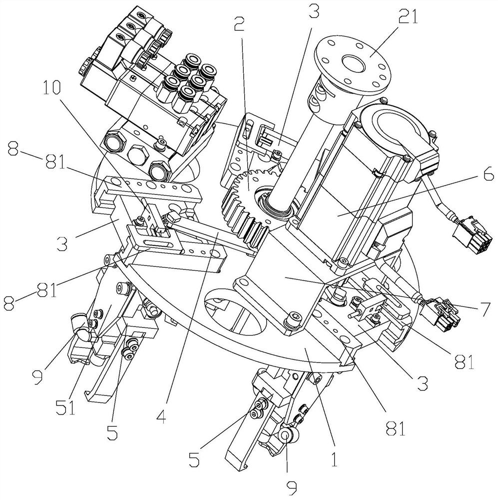
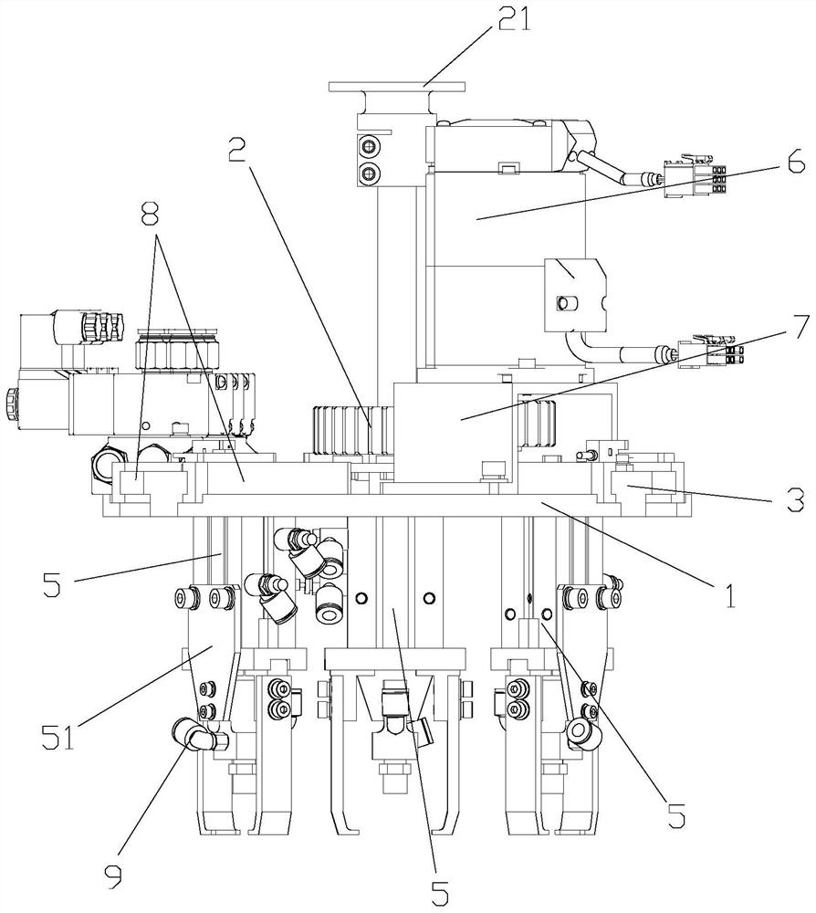
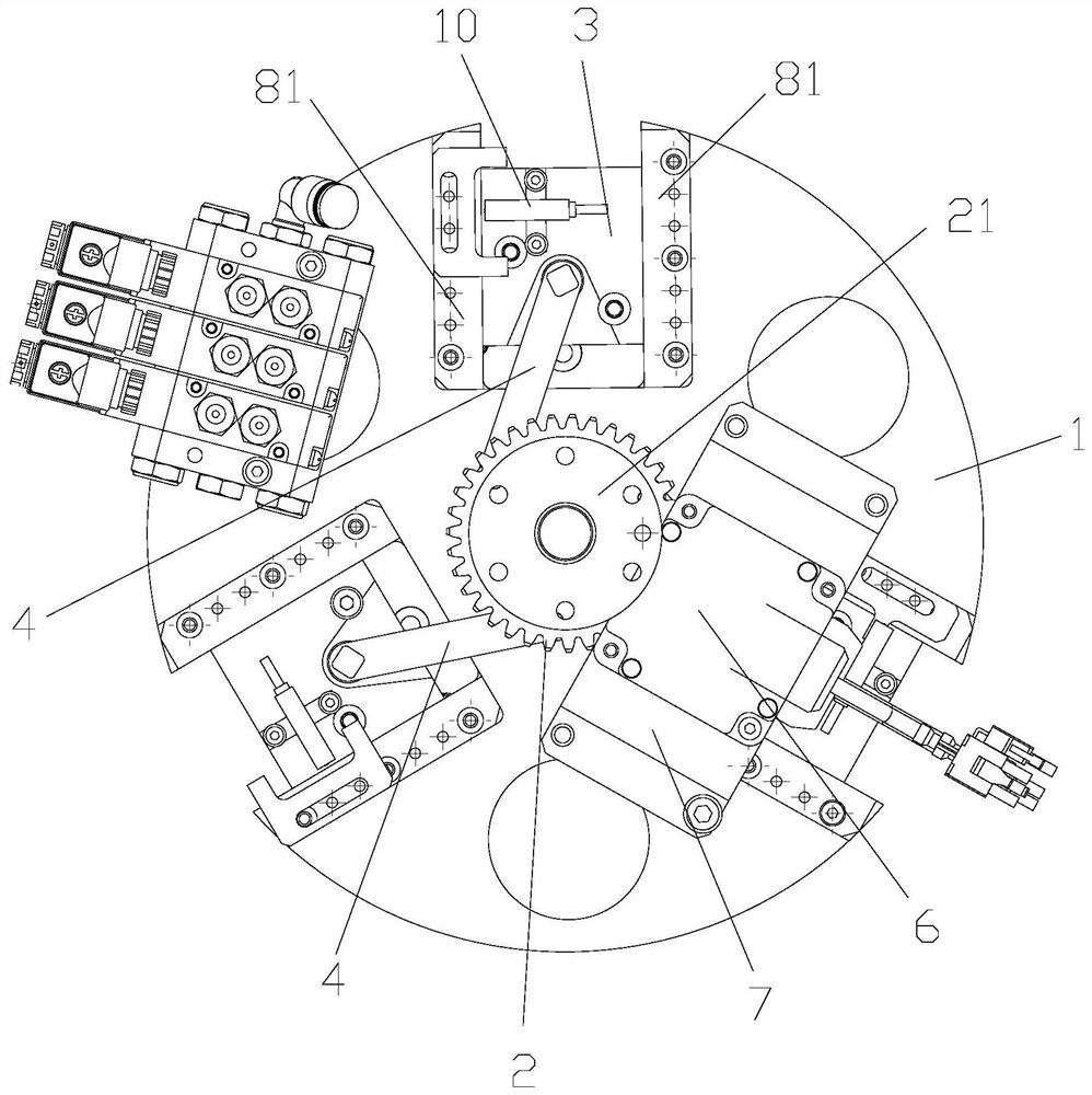
[0023] Please refer to Figure 1 to Figure 3 , the present invention provides a compressor foot pad clamp, comprising: a frame 1; a rotating part 2, which is rotatably arranged on the frame 1 around a predetermined axis; a plurality of movable parts 3, which are arranged on the frame at intervals Frame 1, each movable part 3 is all movably arranged relative to the frame 1; a plurality of transmission parts 4, a plurality of transmission parts 4 and a plurality of movable parts 3 are provided in one-to-one correspondence, and one end of each transmission part 4 is connected to the rotating part 2 are hinged, and the other end of each transmission part 4 is hinged with the corresponding movable ...


PUM


Abstract

The invention provides a compressor foot pad clamp. The compressor foot pad clamp comprises a rack, a rotating piece, a plurality of movable pieces, a plurality of transmission pieces and a pluralityof clamping pieces; the rotating piece is rotatably arranged on the rack around a preset axis; the plurality of movable pieces are arranged on the rack at intervals, and each movable piece is movablyarranged relative to the rack; the plurality of transmission pieces and the plurality of movable pieces are arranged in a one-to-one correspondence mode, one end of each transmission piece is hinged to the rotating piece, and the other end of each transmission piece is hinged to the corresponding movable piece; when the rotating piece rotates relative to the rack, the rotating piece drives the plurality of movable pieces to move through the plurality of transmission pieces so as to change the distance between at least two movable pieces; and the plurality of clamping pieces are installed on the plurality of movable pieces in a one-to-one correspondence mode so that a plurality of compressor foot pads can be grabbed through the plurality of clamping pieces. By means of the compressor foot pad clamp, the problem that in the prior art, a compressor foot pad clamp is poor in universality is solved.

Description

technical field [0001] The invention relates to the field of compressor assembly, in particular to a compressor foot pad clamp. Background technique [0002] During the compressor assembly process, the compressor foot pad fixture is usually used to clamp and automatically assemble the compressor foot pad, so as to improve the assembly efficiency of the compressor. [0003] The existing compressor foot pad fixtures are usually designed separately for specific types of compressors, which can only meet the installation of foot pads for corresponding types of compressors, but cannot be applied to the foot pad assembly process of other types of compressors. There is a problem of poor versatility. Contents of the invention [0004] The main purpose of the present invention is to provide a compressor foot pad clamp to solve the problem of poor versatility of the compressor foot pad clamp in the prior art. [0005] In order to achieve the above object, the present invention prov...

Claims


Application Information

Patent Timeline
IPC IPC(8): B25B11/02
CPCB25B11/02
Inventor 谭畅王健刘超张琪叶祥
Owner ZHUHAI GREE INTELLIGENT EQUIP CO LTD
Why Eureka
Try Eureka