Window glass edge removing and scratching equipment

A scratch and glass technology, which is applied in the field of window glass edge removal and scratch equipment, can solve the problems of manpower time-consuming, low efficiency, difficult operation, etc., and achieve the effect of improving work efficiency and facilitating loading and unloading

Pending Publication Date: 2021-03-19
曹丽源
View PDF6 Cites 0 Cited by
  • Summary
  • Abstract
  • Description
  • Claims
  • Application Information

AI Technical Summary

Problems solved by technology

[0005] In order to overcome the shortcomings of time-consuming manpower, low efficiency, and difficult operation, t

Method used


Image

  • Window glass edge removing and scratching equipment
  • Window glass edge removing and scratching equipment
  • Window glass edge removing and scratching equipment

Examples


Embodiment 1

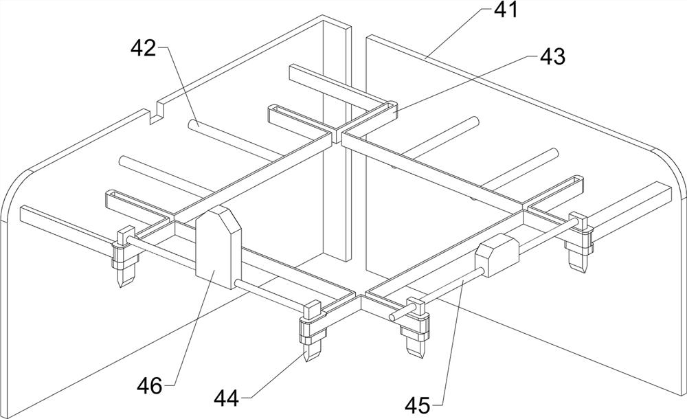
[0031] A kind of window glass edge scraping equipment, such as figure 1 , figure 2 , image 3, Figure 4 and Figure 5 As shown, it includes a base 1, a support frame 2, a fixed assembly 3, a scratch assembly 4 and a rising assembly 5, a support frame 2 is provided in the middle of the upper part of the base 1, a fixed assembly 3 is provided between the front and rear sides of the support frame 2, and the base 1 is provided with a scratch assembly 4 on the left side of the upper part, and a lifting assembly 5 is provided at the upper left part of the base 1.

[0032] When the user needs to remove the edges and scratches on the window glass, first put the glass on the fixed assembly 3, step on the lifting assembly 5, and drive the scratch assembly 4 to move, so that the glass is removed and scratched, and then the glass is removed , Unified collection, to achieve the effect of automatically removing scratches for the glass.

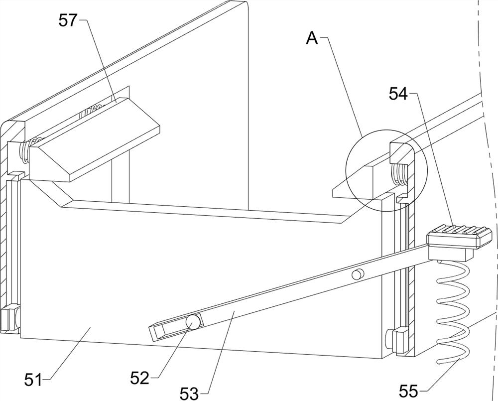
[0033] The fixing assembly 3 includes a first ...

Embodiment 2

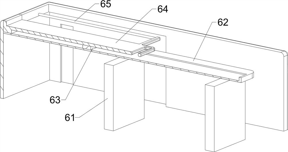
[0040] On the basis of Example 1, such as Figure 6 , Figure 7 , Figure 8 , Figure 9 and Figure 10 As shown, an auxiliary discharge assembly 6 is also included, and the auxiliary discharge assembly 6 includes a fourth support plate 61, a second slide rail 62, a slider 63, a movable plate 64 and a fourth connecting rod 65, and the upper right side of the base 1 and the middle are connected with a fourth support plate 61, the upper side of the fourth support plate 61 is connected with a second slide rail 62, the left side of the second slide rail 62 is connected with the left side of the support frame 2, and the upper side of the second slide rail 62 Slide block 63 is connected to the side slide type, and movable plate 64 is connected to the upper side of slide block 63, and the fourth connecting rod 65 is connected symmetrically front and rear on the right side of movable plate 64, and the fourth connecting rod 65 is slidingly connected to the left side of support frame ...


PUM


Abstract

The invention relates to scratching equipment, in particular to window glass edge removing and scratching equipment. The window glass edge removing and scratching equipment is automatic, efficient andeasy and convenient to operate. The window glass edge removing and scratching equipment comprises a base, a fixing assembly arranged between the two sides of the supporting frame, a scratching assembly arranged on one side of the base, and an ascending assembly arranged on one side of the base; and a supporting frame is arranged in the middle of the upper portion of the base. Glass is placed on amovable plate, and the movable plate is pushed to move towards the left side and the right side, so that the glass is conveyed, and the effect of facilitating feeding and discharging is achieved. A pedal is treaded to drive a first wedge-shaped block and a second wedge-shaped block to move in a matched mode, so that a second supporting plate moves upwards, a suction cup sucks glass and pushes other cutter blocks to make contact with the glass, the effect of automatically fixing and loosening the glass is achieved, and it is guaranteed that glass edge removing and scratching are conducted smoothly.

Description

technical field [0001] The invention relates to a scratching device, in particular to a window glass edge-removing scratching device. Background technique [0002] Window, in architecture, refers to the hole built on the wall or roof to allow light or air to enter the room. With the continuous development of science and technology, people have already abandoned the paper material of ancient windows, and found a more suitable material glass to construct Windows, on the basis of ensuring a certain resistance to wind and cold, can also allow light to enter the room smoothly. [0003] At present, the windows in the family are basically square, so in order to obtain windows suitable for different sizes, it is necessary to remove the edge and scratch the original glass, so as to obtain square glass of different sizes. Edge scratching is a completely manual process. Taking the finished glass as a reference, on the glass raw material, manually scratch along the edge with a glass kn...

Claims


Application Information

Patent Timeline
IPC IPC(8): C03B33/02
CPCC03B33/02
Inventor 曹丽源
Owner 曹丽源
Why Eureka
Try Eureka