Clamping device for base plate

A technology of clamping mechanism and substrate

Inactive Publication Date: 2010-02-24
DONGGUAN ANWELL DIGITAL MASCH CO LTD
View PDF1 Cites 8 Cited by
  • Summary
  • Abstract
  • Description
  • Claims
  • Application Information

AI Technical Summary

Problems solved by technology

At present, most of the substrate clamping mechanisms at home and abroad are stepped support mechanisms. This technology is mainly reflected in the Chinese invention patent with the publication number CN1901155A, which discloses a clamper with multiple stepped support plates. The clamper uses the edge to constrain the position of the substrate, so as to realize the clamping of the substrate. The clamper can clamp multiple substrates at the same time, but the clamper can only realize the planar transfer of the substrate, and cannot realize the flipping of the substrate. , and the step-type support mechanism is a plurality

Method used


Image

  • Clamping device for base plate
  • Clamping device for base plate
  • Clamping device for base plate

Examples


Embodiment Construction

[0022] Embodiments of the present invention will now be described with reference to the drawings, in which like reference numerals represent like elements.

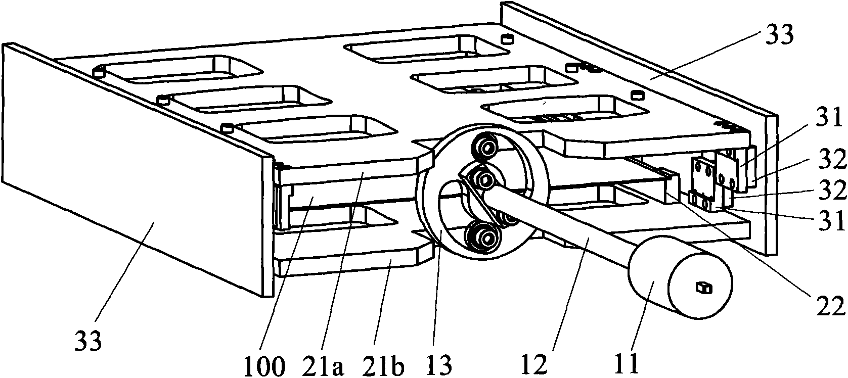
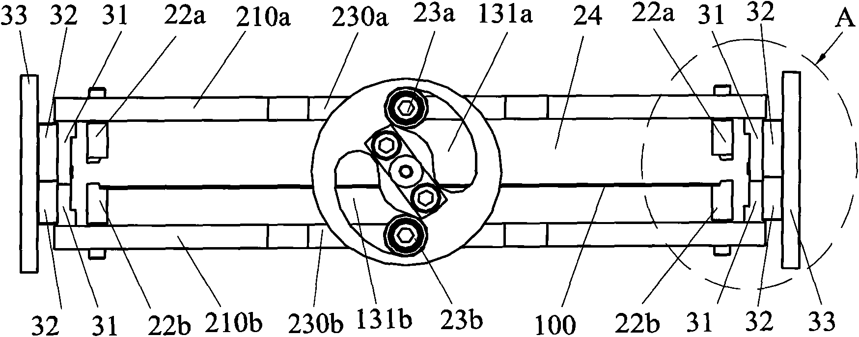
[0023] refer to Figure 1-2 , the substrate clamping mechanism of the present invention includes a driving device, the driving device includes a transmission shaft 12, a cam 13 and a driving mechanism 11 providing a power source, and the cam 13 is symmetrically provided with two arc-shaped guide grooves 131a, 131b, so One end of the transmission shaft 12 is fixedly connected to the driving mechanism 11, and the other end is fixedly connected to the cam 13, and the driving device provides power for clamping or loosening the substrate 100; the clamping device includes an upper , lower pressing plate 21a, 21b and at least one pair of pressing bar group 22, described pressing bar group 22 comprises upper and lower pressing bar 22a, 22b, each is installed on the corresponding side 210a, 210b of described upper and lower pressi...


PUM


Abstract

The invention discloses a clamping device for a base plate, comprising a driving device, a clamping device and a fixing guiding mechanism. The driving device comprises a power supply, a cam provided with two arc guide grooves, and a transmission shaft with one end connected to the power supply and the other end connected to the cam. The clamping device comprises an upper pressure pad, a lower pressure pad, an upper treadle bar, and a lower treadle bar, wherein a circular roller driven member in the two arc guide grooves is respectively disposed on the side walls corresponding to the upper andthe lower pressure pads. A clamping region is formed between the upper and the lower pressure pads. The upper treadle bar is arranged on the upper pressure pad and the lower treadle bar is arranged onthe lower pressure pad. The sliding directions of a guide way and a sliding block are vertical to the upper and the lower pressure pads. The clamping device for base plate has the advantages of stable operation for transmitting and turning over the base plate, simple structure, convenient operation, etc.

Description

technical field [0001] The invention relates to a clamping mechanism, in particular to a substrate clamping mechanism of an organic light-emitting display device. Background technique [0002] With the continuous development of the economy, the continuous advancement of science and technology and the decrease of world energy, people pay more and more attention to energy conservation and utilization efficiency in production, so that the harmonious development of man and nature can meet the requirements of China's new industrialization road. [0003] For example, in the display industry of digital products, in order to save energy and reduce production costs, enterprises have increased investment in research and development, and are constantly pursuing new energy-saving products. Among them, OLED display screen is a new product in digital products. OLED is Organic Light-Emitting Diode (Organic Light-Emitting Diode). And it has great market potential. At present, the applicati...

Claims


Application Information

Patent Timeline
IPC IPC(8): H01L21/687H01L51/56
CPCH01L21/68728
Inventor 杨明生范继良雷振宇王曼媛王勇
Owner DONGGUAN ANWELL DIGITAL MASCH CO LTD
Why Eureka
Try Eureka