Cutting device for electric wire machining

A wire and cable cutting device technology, applied in the field of wire and cable processing cutting devices, can solve the problems of low pass rate of finished products, achieve the effects of improving accuracy and pass rate, shortening stroke, and preventing inaccurate cutting

Active Publication Date: 2018-10-19
陕西润瀚电气科技有限公司
View PDF7 Cites 8 Cited by
  • Summary
  • Abstract
  • Description
  • Claims
  • Application Information

AI Technical Summary

Problems solved by technology

[0005] The purpose of the present invention is to provide a cutting device for wire and cable processing to solve the problem in the prior art that the qualified rate of finished products after processing is low due to improper cutting of the wire and cable cutting device

Method used


Image

  • Cutting device for electric wire machining
  • Cutting device for electric wire machining
  • Cutting device for electric wire machining

Examples


Embodiment Construction

[0026] The following is further described in detail through specific implementation methods:

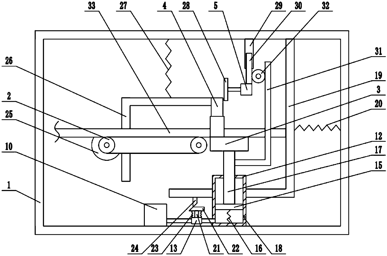
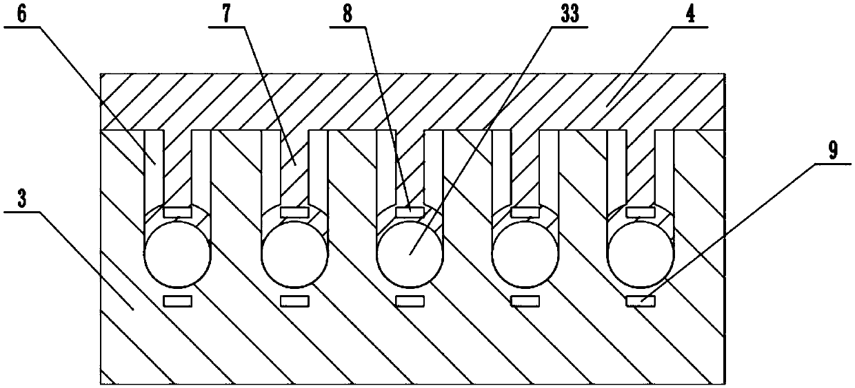
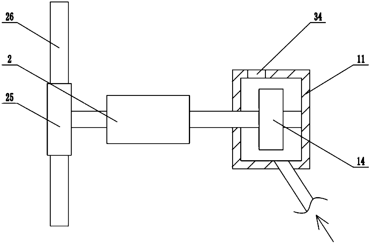
[0027] The reference signs in the drawings of the description include: frame 1, driving wheel 2, workbench 3, limit plate 4, motor 5, limit groove 6, protrusion 7, first magnet 8, second magnet 9, supply Bellows 10, wind guide box 11, cylinder body 12, three-way valve 13, turbine 14, piston 15, first spring 16, piston rod 17, air outlet 18, positioning plate 19, third spring 20, valve stem 21, first One wedge 22, the fourth spring 23, the second wedge 24, ratchet 25, transmission rod 26, second spring 27, cutter 28, outer sleeve rod 29, inner sleeve rod 30, rack 31, gear 32, wire and cable 33, air outlet 34.

[0028] The embodiment is basically as attached Figure 1 to Figure 3 Shown:

[0029]The cutting device for wire and cable processing includes a frame 1, on which a transmission mechanism is arranged, and the transmission mechanism includes a driving wheel 2, a driven wheel a...


PUM


Abstract

The invention relates to the technical field of electric wire machining, and discloses a cutting device for electric wire machining. The cutting device comprises a rack. A conveying mechanism is arranged on the rack and comprises a driving wheel. A workbench, a limiting plate and a cutting mechanism are in sliding connection to the rack. Multiple limiting grooves used for containing electric wiresare formed in the workbench. A first drive mechanism used for driving the limiting plate to slide is arranged on the rack. An air supply box, an air guide box and a cylinder body are fixedly connected to the rack. A first guide pipe communicates between the air supply box and the air guide box, and a three-way valve is arranged on the guide pipe. A second guide pipe is connected between the cylinder body and the three-way valve. A turbine coaxially connected with the driving wheel is rotationally connected in the air guide box. A piston is in sliding connection in the cylinder body. A first spring is connected between the piston and the cylinder body. A piston rod fixedly connected with the workbench is fixedly connected to the piston. An air outlet hole is formed in the cylinder body. The cutting device solves the problem that in the prior art, due to improper cutting, the percent of pass of finished products of an electric wire cutting device after machining is low.

Description

technical field [0001] The invention relates to the technical field of wire and cable processing, in particular to a cutting device for wire and cable processing. Background technique [0002] Wire and cable are wire products that transmit electrical energy, electrical signals and realize electromagnetic energy conversion. Cables usually consist of a core for transmitting power or electrical signals and a sheath for protection and insulation. A cable with a single core and a small diameter is often called a wire. The core in the cable is made of a metallic material with good electrical conductivity, usually copper (good electrical conductivity) or aluminum (lower cost). When producing wires and cables, they need to be cut into segments of different lengths according to different needs. The traditional wire and cable cutting equipment includes a cutter, a workbench and a motor for driving the cutter. The wires and cables are placed on the workbench, not only the cutting ef...

Claims


Application Information

Patent Timeline
Patent Type & Authority Applications(China)
IPC IPC(8): B21F11/00B21F23/00
CPCB21F11/00B21F23/00
Inventor 张先渝
Owner 陕西润瀚电气科技有限公司
Why Eureka
Try Eureka