Defrosting mechanism of refrigeration equipment

A technology of refrigeration equipment and compressors, which is applied in refrigerators, defrosting, refrigeration components, etc., which can solve the problems of reduced cooling effect, inconvenient large-area defrosting, and low defrosting efficiency, so as to achieve convenient distance adjustment and improve defrosting effect, the effect of reducing energy consumption

Inactive Publication Date: 2021-03-19
浙江山鹰制冷科技有限公司
View PDF6 Cites 1 Cited by
  • Summary
  • Abstract
  • Description
  • Claims
  • Application Information

AI Technical Summary

Problems solved by technology

[0003] However, during the long-term cooling process of the evaporator, the surface temperature of the evaporator is low, so the water vapor in the environment is easy to frost on the surface of the evaporator. When the amount of frost is large, it is easy to block the gap between the heat exchange fins on the evaporator. , so that the airflow generated by the fan cannot pass through the heat exchange fins, resulting in a serious reduction in the cooling effect. Therefore, the current common practice is to install electric heating wires on the side of the evaporator for heating
[0004] In view of the above-mentioned related technologies, the inventor believes that the direct heating of the electric heating wire consumes a lot of heating energy, and it is not convenient for large-scale defrosting, resulting in low defrosting efficiency

Method used


Image

  • Defrosting mechanism of refrigeration equipment
  • Defrosting mechanism of refrigeration equipment
  • Defrosting mechanism of refrigeration equipment

Examples


Embodiment Construction

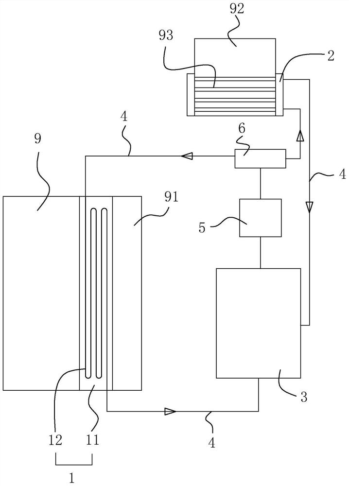
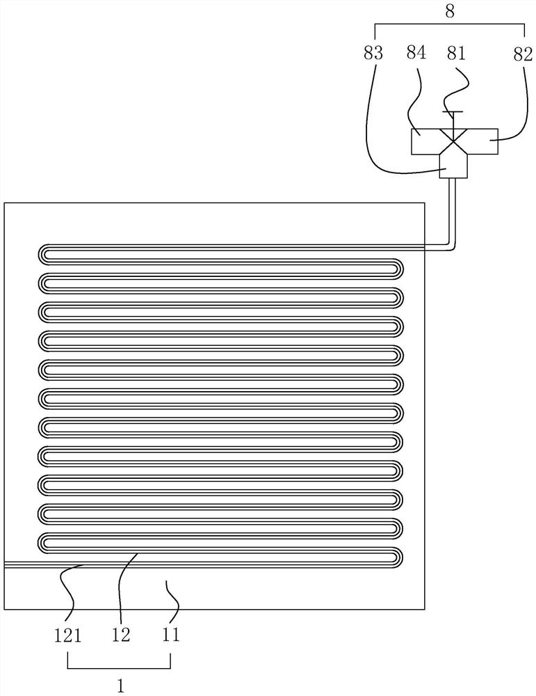
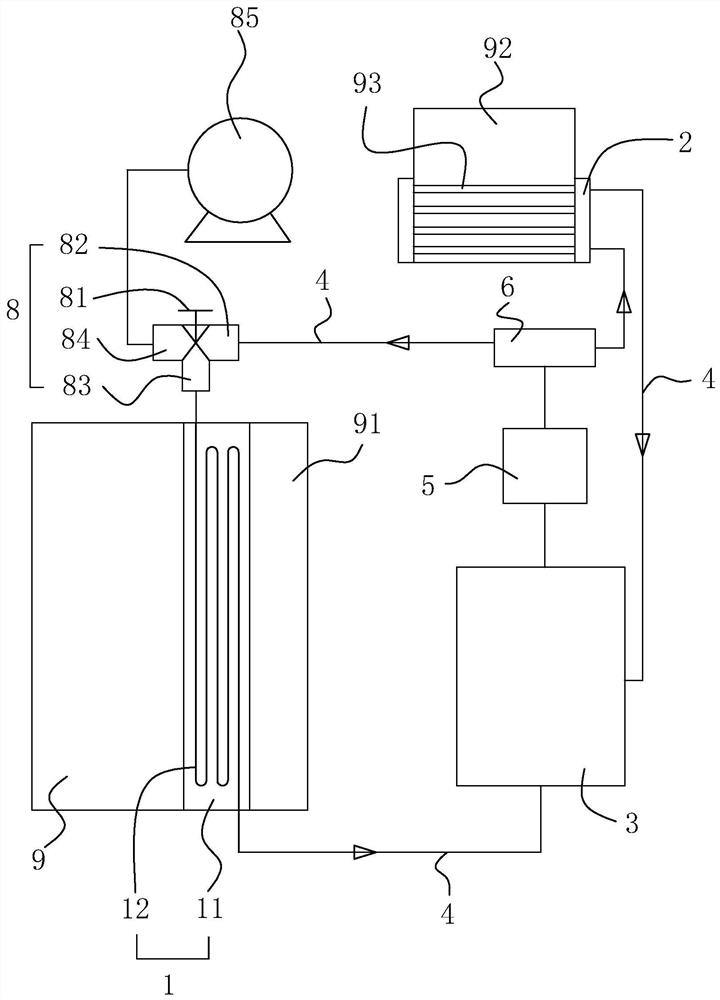
[0036] The following is attached Figure 1-4 The application is described in further detail.

[0037] The refrigerating equipment mainly includes a compressor 92, an evaporator 9, a condenser, a refrigerant storage tank, a filter, and an expansion valve, in which each component is connected through a liquid infusion pipe, and the refrigerant is compressed by the compressor 92 to make the refrigerant flow in the evaporator 9 and The heat between the condenser and the outside air is better, so that the evaporator 9 absorbs heat to the outside to achieve the cooling effect, and the condenser emits heat to the outside to achieve the heating effect, wherein the evaporator 9 and the condenser are equipped with a fan 91. 91 enhances the air flow at the position of the evaporator 9 and the condenser, thereby improving the heat exchange effect and efficiency with the outside world, wherein the surface of the evaporator 9 is relatively low in temperature, and external water vapor is eas...


PUM


Abstract

The invention relates to a defrosting mechanism of refrigeration equipment. The defrosting mechanism comprises a defrosting portion, a heat collecting portion, a liquid storing box, a connecting pipeand a circulating pump. The defrosting portion is arranged on an evaporator. The heat collecting portion is arranged on a compressor. The liquid storing box is connected with a circulating pump. The circulating pump conveys cooling liquid for the defrosting portion and the heat collecting portion through a connecting pipe. A pipeline switching valve is connected to the circulating pump. Accordingto the mechanism, heat generated in the normal working process of the compressor is utilized for heating the cooling liquid, and when the evaporator needs to be defrosted, the cooling liquid with theheat is introduced into the defrosting portion to carry out defrosting for the evaporator. In the defrosting process, the heat dissipating temperature of the cooling liquid is lowered, then when the refrigeration equipment works normally, the low-temperature cooling liquid can dissipate the heat for the compressor efficiently. Therefore, the evaporator is effectively defrosted, and the energy consumption is effectively reduced.

Description

technical field [0001] The present application relates to the field of refrigeration equipment manufacturing, in particular to a refrigeration equipment defrosting mechanism. Background technique [0002] Due to the high demand for refrigeration and indoor cooling in people's production and life, cold storage and air conditioning are widely used. The core components of air conditioning and cold storage are refrigeration equipment, which mainly include compressors, evaporators, and condensers. , Refrigerant storage tank, filter, and expansion valve, all of which are connected by a liquid infusion pipe, and the refrigerant is compressed by the compressor, so that the refrigerant can be heated better with the external air in the evaporator and condenser, so that the evaporator can be heated to the outside world Absorb heat to achieve refrigeration, and the condenser emits heat to the outside to achieve heating. [0003] However, during the long-term cooling process of the evap...

Claims


Application Information

Patent Timeline
Patent Type & Authority Applications(China)
IPC IPC(8): F25B47/02F25D21/08
CPCF25B47/02F25D21/08
Inventor 周启辉
Owner 浙江山鹰制冷科技有限公司
Why Eureka
Try Eureka