Strength detection device for circuit board production

A technology for strength testing and circuit boards, which is applied in the direction of measuring devices, strength characteristics, and the use of stable tension/pressure testing material strength, etc., can solve the inconvenience of quickly clamping and fixing two circuit boards, lack of comparison, and inconvenient alignment. Problems such as different detection positions of circuit boards of different sizes

Active Publication Date: 2021-03-19
益阳市明正宏电子有限公司
View PDF24 Cites 2 Cited by
  • Summary
  • Abstract
  • Description
  • Claims
  • Application Information

AI Technical Summary

Problems solved by technology

[0003] However, the design of the traditional strength testing device for circuit board production still has shortcomings. It is not convenient to quickly clamp and fix two circuit boards at the same time, the detection efficiency is low, and there is no comparison. In addition, the detection head is not easy to carry out Mobile and fixed, it is not convenient to align different detection positions of circuit boards of different sizes, which brings a lot of trouble to the detection work

Method used


Image

  • Strength detection device for circuit board production
  • Strength detection device for circuit board production
  • Strength detection device for circuit board production

Examples


no. 1 example

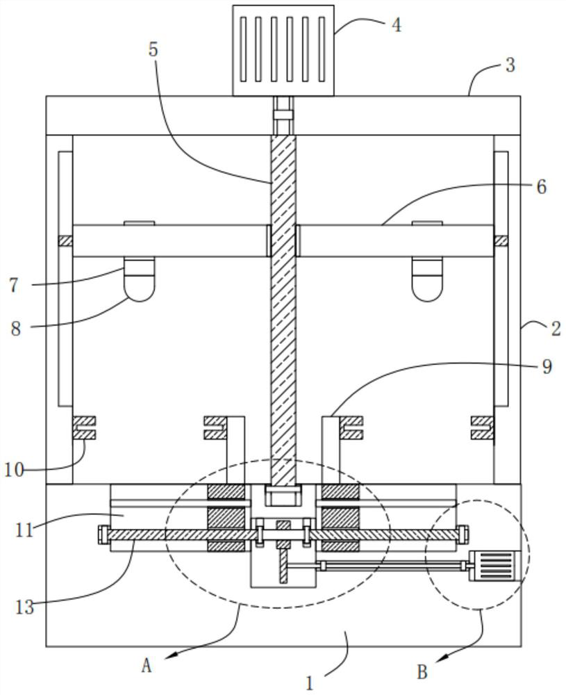
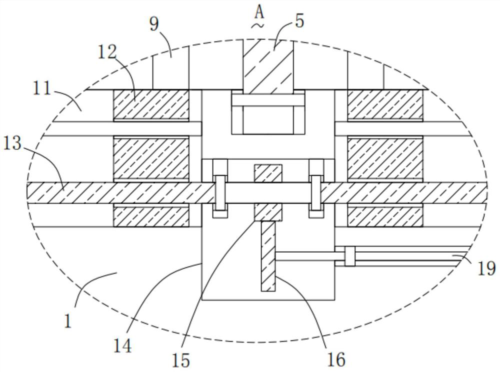
[0025] Please refer to Figure 1-3, in the first embodiment of the present invention, the strength detection device for circuit board production includes: a base 1; two support columns 2, and the two support columns 2 are fixedly installed on the top of the base 1; a horizontal plate 3, the The horizontal plate 3 is fixedly installed on the top of the two supporting columns 2; the first motor 4 is fixedly installed on the top of the horizontal plate 3; the first screw 5 is mounted on the base in rotation 1 and the cross plate 3, the output shaft of the first motor 4 is fixedly connected with the top end of the first screw rod 5; the cross bar 6 is slidably installed on the two supporting columns 2, and the first screw rod 5 is threadedly installed on the On the cross bar 6, the first screw rod 5 runs through the cross bar 6; two pressure sensing assemblies 7, the two pressure sensing assemblies 7 are arranged at the bottom of the cross bar 6, and the first screw rod 5 is locat...

no. 2 example

[0038] Based on the strength detection device for circuit board production provided in the first embodiment of the present application, the second embodiment of the present application proposes another strength detection device for circuit board production. The second embodiment is only a preferred mode of the first embodiment, and the implementation of the second embodiment will not affect the independent implementation of the first embodiment.

[0039] The second embodiment of the present invention will be further described below in conjunction with the drawings and implementation methods.

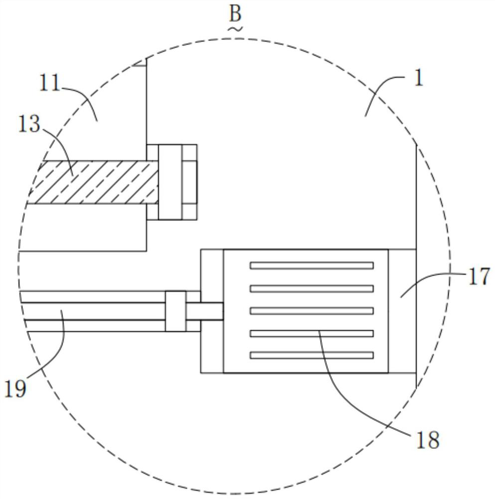
[0040] Please refer to Figure 4-5 The strength detection device for circuit board production also includes two sliding sleeves 20, the two sliding sleeves 20 are all slidingly sleeved on the cross bar 6, the first screw rod 5 is located between the two sliding sleeves 20, and the pressure sensing assembly 7 is fixedly installed on the bottom of the corresponding sliding sleeve 20, and ...


PUM


Abstract

The invention provides a strength detection device for circuit board production. The strength detection device for circuit board production comprises: a base; two supporting columns, which are fixedlymounted at the top of the base; a transverse plate, which is fixedly mounted at the top ends of the two supporting columns; a first motor, which is fixedly mounted at the top of the transverse plate;a first screw rod, which is rotationally installed on the base and the transverse plate, wherein an output shaft of the first motor is fixedly connected with the top end of the first screw rod; a cross rod, which is installed on the two supporting columns in a sliding mode, wherein the first screw rod is installed on the cross rod in a threaded mode. The strength detection device for circuit board production has the advantages that use is convenient, operation is easy, two circuit boards can be conveniently and rapidly clamped and fixed, the detection efficiency can be effectively improved, comparison is convenient, a detection head is convenient to move and fix, and the requirement for detecting different positions of the circuit boards of different sizes can be met.

Description

technical field [0001] The invention relates to the technical field of circuit board production, in particular to a strength detection device for circuit board production. Background technique [0002] The circuit board is also called the printed circuit board. The circuit board makes the circuit miniaturized and intuitive. It plays an important role in the mass production of fixed circuits and the optimization of the layout of electrical appliances. With the continuous development of science and technology, a large number of electronic products are produced. People The demand for circuit boards is also increasing day by day. In the production process of circuit boards, strength testing devices are needed to test their strength. Traditional circuit board production strength testing is basically done by multiple bending methods. . [0003] However, the design of the traditional strength testing device for circuit board production still has shortcomings. It is not convenient ...

Claims


Application Information

Patent Timeline
Patent Type & Authority Applications(China)
IPC IPC(8): G01N3/08G01N3/04
CPCG01N3/08G01N3/04Y02W30/82
Inventor 徐正武祝文贵陈泽和
Owner 益阳市明正宏电子有限公司
Why Eureka
Try Eureka