Optical imaging system, image capturing module and electronic device

An optical imaging system and optical technology, applied in optics, optical components, instruments, etc., can solve the problems of poor image quality, thick wide-angle optical lens, and unsatisfactory thinning and miniaturization of electronic equipment, so as to improve image quality and reduce Manufacturing cost, satisfying the effect of external beautification

Inactive Publication Date: 2021-03-19
JIANGXI JINGCHAO OPTICAL CO LTD
View PDF0 Cites 5 Cited by
  • Summary
  • Abstract
  • Description
  • Claims
  • Application Information

AI Technical Summary

Problems solved by technology

[0003] Wide-angle optical lenses have a better sense of scene substitution and are more widely used. However, in the process of implementing this application, the inventors found that there are at least the following problems in the prior art: wide-angle optical lenses are generally thick, which does not meet the requirements of light and thin electronic equipment. In order to achieve the wide-angle function of the optical lens, most of the lenses are made of high refractive index materials, which increases the cost of the optical lens

Method used


Image

  • Optical imaging system, image capturing module and electronic device
  • Optical imaging system, image capturing module and electronic device
  • Optical imaging system, image capturing module and electronic device

Examples


no. 1 example

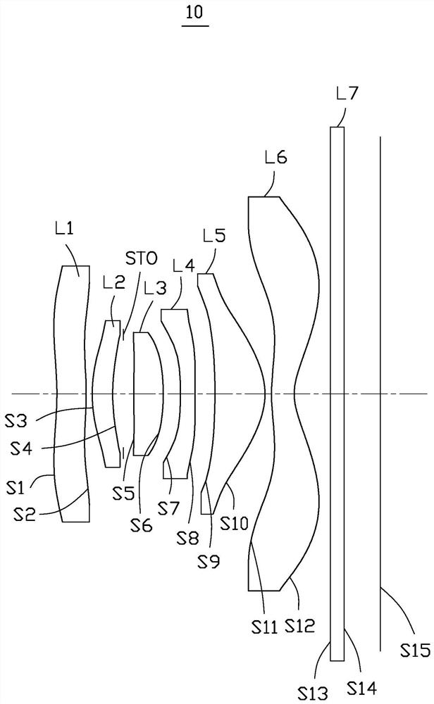
[0127] Please refer to figure 1 and figure 2 , the optical imaging system 10 of the first embodiment includes a first lens L1 with positive refractive power, a second lens L2 with positive refractive power, a diaphragm STO, and a third lens with positive refractive power from the object side to the image side L3, a fourth lens L4 with negative refractive power, a fifth lens L5 with positive refractive power, a sixth lens L6 with negative refractive power, and an infrared filter L7.

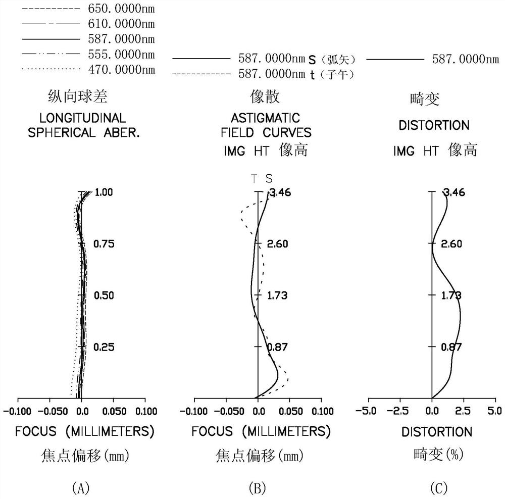
[0128] See figure 2 , figure 2 Shows the spherical aberration curves of the optical imaging system 10 at wavelengths of 650nm, 610nm, 587nm, 555nm, and 470nm, the astigmatism of light at a wavelength of 587nm, and the distortion curve at a wavelength of 587nm of the optical imaging system 10 in the first embodiment, And the optical imaging system 10 in the first embodiment satisfies the conditions in Table 1 and Table 2 below.

[0129] Wherein, the object side S1 of the first lens L1 is con...

no. 2 example

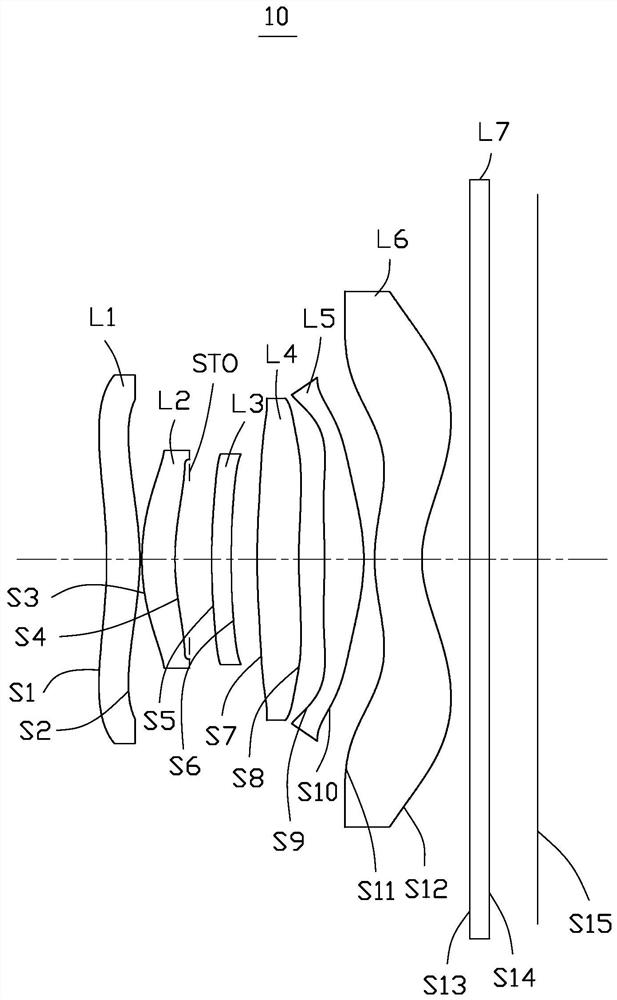
[0144] Please refer to image 3 and Figure 4 , the optical imaging system 10 of the second embodiment includes a first lens L1 with positive refractive power, a second lens L2 with negative refractive power, an aperture STO, and a third lens with positive refractive power from the object side to the image side. L3, a fourth lens L4 with negative refractive power, a fifth lens L5 with positive refractive power, a sixth lens L6 with negative refractive power, and an infrared filter L7.

[0145] Wherein, the object side S1 of the first lens L1 is concave at the near optical axis, and the image side S2 is convex at the near optical axis; the object side S3 of the second lens L2 is convex at the near optical axis, and the image side S4 is convex at the near optical axis. The optical axis is concave; the object side S5 of the third lens L3 is concave at the near optical axis, and the image side S6 is convex at the near optical axis; the object side S7 of the fourth lens L4 is conc...

no. 3 example

[0160] Please refer to Figure 5 and Figure 6 , the optical imaging system 10 of the third embodiment includes a first lens L1 with positive refractive power, a second lens L2 with positive refractive power, a diaphragm STO, and a third lens with positive refractive power from the object side to the image side L3, a fourth lens L4 with positive refractive power, a fifth lens L5 with positive refractive power, a sixth lens L6 with negative refractive power, and an infrared filter L7.

[0161] Wherein, the object side S1 of the first lens L1 is concave at the near optical axis, and the image side S2 is convex at the near optical axis; the object side S3 of the second lens L2 is convex at the near optical axis, and the image side S4 is convex at the near optical axis. The optical axis is concave; the object side S5 of the third lens L3 is convex at the near optical axis, and the image side S6 is concave at the near optical axis; the object side S7 of the fourth lens L4 is conve...


PUM


Abstract

The invention provides an optical imaging system, an image capturing module and an electronic device. The optical imaging system comprises a first lens element with positive refractive power, a secondlens element with refractive power, a third lens element with positive refractive power, a fourth lens element with refractive power, a fifth lens element with positive refractive power, and a sixthlens element with negative refractive power, the object-side surface of the sixth lens element being convex in a paraxial region and the image-side surface being convex in a paraxial region, and at least one of the object-side surface and the image-side surface of the sixth lens element being provided with at least one inflection point; the optical imaging system meets the relational expression: 3.9 / mm < (IND2+IND3+IND4+IND5+IND6) / SD1 < 7.0 / mm, wherein IND2 to IND6 are the refractive indexes from the second lens element to the sixth lens element respectively, and SD1 is the vertical distance from the optical effective diameter position of the object-side surface of the first lens element to the optical axis. According to the optical imaging system, the plurality of lens elements with low refractive indexes are matched, a wide-angle function can be realized, the cost is saved, the thickness of the optical imaging system is relatively small by reasonably configuring the refractive powerof each lens element, and high-pixel and high-quality imaging is supported.

Description

technical field [0001] The invention relates to optical imaging technology, in particular to an optical imaging system, an imaging module and an electronic device. Background technique [0002] At present, with the development of science and technology, smart electronic devices are becoming popular in people's daily life, especially electronic devices with diversified camera functions, such as smart terminals with wide-angle camera functions. Most of the front wide angles of existing electronic devices are less than 84°, and the size of the captured object space is quite different from the viewing angle of the human eye, so the daily use scenarios are limited. [0003] Wide-angle optical lenses have a better sense of scene substitution and are more widely used. However, in the process of implementing this application, the inventors found that there are at least the following problems in the prior art: wide-angle optical lenses are generally thick, which does not meet the req...

Claims


Application Information

Patent Timeline
Patent Type & Authority Applications(China)
IPC IPC(8): G02B13/00G02B13/18
CPCG02B13/0015G02B13/0045
Inventor 刘彬彬党绪文李明邹海荣
Owner JIANGXI JINGCHAO OPTICAL CO LTD
Why Eureka
Try Eureka