
Automatic detection equipment for computer memory banks

A technology for automatic detection and memory sticks, which is applied in static memory, instruments, etc., and can solve the problems of complicated opening and detection slots and buckles.

Active Publication Date: 2021-03-19
武汉攀升鼎承科技有限公司
View PDF5 Cites 1 Cited by
  • Summary
  • Abstract
  • Description
  • Claims
  • Application Information

AI Technical Summary

Problems solved by technology

[0007] In order to overcome the problem that the existing memory stick detection equipment requires a person to manually put the memory stick to be tested into a designated position for subsequent testing, and can only perform a single detection on the memory sticks one by one, and it is too complicated to open the detection slot buckle , the present invention provides an automatic detection device for computer memory sticks that can continuously automatically detect multiple performances of multiple memory sticks, and is convenient and safe to open the buckle of the detection slot. The upper and lower ends of the memory stick to be tested are plugged together with the detection slot, and an unlocking mechanism consisting of a cylindrical stopper is set on the rotation path of the detection slot to smoothly open the rotating buckle to facilitate the locking of the memory stick

Method used


Image

  • Automatic detection equipment for computer memory banks
  • Automatic detection equipment for computer memory banks
  • Automatic detection equipment for computer memory banks

Examples


Embodiment 1

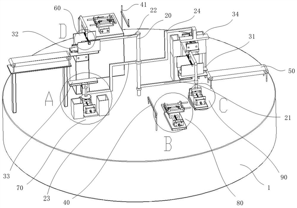
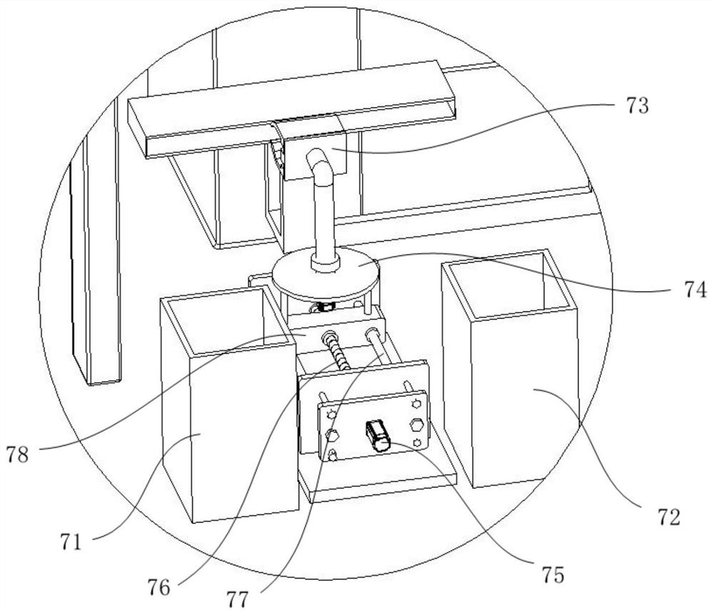
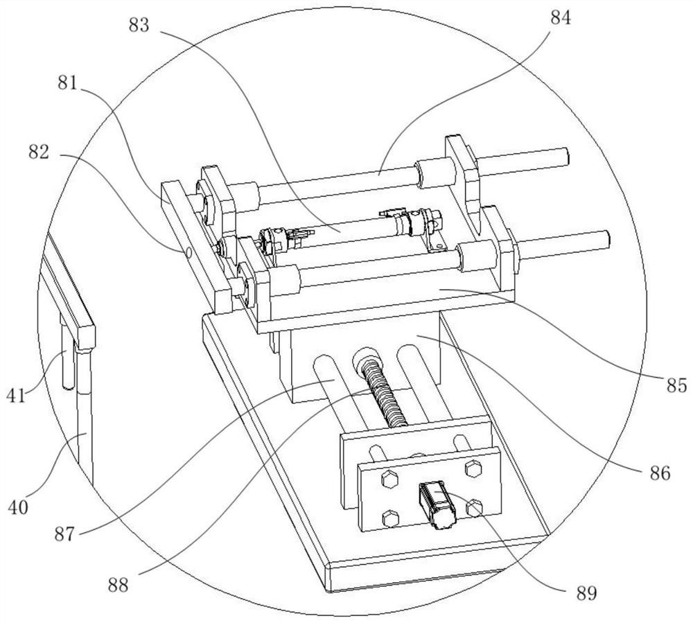
[0045] Such as figure 1 As shown, an automatic detection equipment for computer memory bars includes a detection table 1, a rotary device arranged above the detection table 1, a feeding device and an unloading device respectively arranged on the upper and lower sides of the rotary device. The detection platform 1 is provided with a PLC control assembly inside, and the rotary device includes a material delivery mechanism and a detection mechanism that are rotatably connected. Drive, when the rotary motor is working, the material delivery mechanism and the detection mechanism move relatively, so that the memory stick to be detected and the detection slot are plugged after rotating 90°, and the left and right sides of the material delivery mechanism are arranged symmetrically There are material delivery boxes, which are respectively located at the lower right and upper left of the material delivery mechanism. There are detection slots at the left and right symmetrical positions o...


PUM


Abstract

The invention discloses automatic detection equipment for computer memory banks which comprises a detection table, a rotation device arranged above the detection table, a feeding device and a discharging device, and the feeding device and the discharging device are arranged above and below the two sides of the rotation device respectively. A PLC control assembly is arranged in the interior of thedetection table. The rotating device comprises a material conveying mechanism and a detection mechanism which are rotationally connected, the material conveying mechanism and the detection mechanism are opposite in rotating direction and are driven by a motor arranged in the detection table, and material conveying boxes are symmetrically arranged on the left side and the right side of the materialconveying mechanism in a central symmetry mode. Detection inserting grooves are formed in the left-right symmetrical positions of the detection mechanism and the material conveying mechanism, and anunlocking mechanism used for opening buckles arranged on the two sides of the detection inserting grooves is arranged between the material conveying mechanism and the detection mechanism. By means ofthe mode, the automatic detection equipment for the computer memory banks is simple in structure and capable of feeding, detecting and discharging the memory banks in a full-automatic mode.

Description

technical field [0001] The invention relates to the field of automatic detection, in particular to automatic detection equipment for computer memory sticks. Background technique [0002] As computers became more popular, so did the scale of their production. As an indispensable part of the computer, the memory stick has high standards for its production quantity and quality. In industrial production, the memory stick is usually tested from the following two aspects. The first is performance testing. The memory stick is inserted into the detection slot and connected to a computer for performance testing, followed by a pull-out force test. Only when both meet the standards can the memory stick be shipped from the factory. [0003] Nowadays, the detection of memory sticks on the existing market is usually to detect the insertion and removal force of the memory stick unilaterally, and its performance cannot be tested at the same time. Then plug the two after opening, but most ...

Claims


Application Information

Patent Timeline
IPC IPC(8): G11C29/56
CPCG11C29/56
Inventor 宋安阳
Owner 武汉攀升鼎承科技有限公司
Learn More