A power detection circuit and method of a power amplifier

A technology of power detection circuit and power amplifier, which is applied in the direction of power amplifiers, amplifiers, parts of amplifiers, etc., and can solve the problems of limited range of power amplifiers, single compensation function, and low flexibility.

Active Publication Date: 2021-05-14
GUANGZHOU HUIZHI MICROELECTRONICS
View PDF6 Cites 0 Cited by
  • Summary
  • Abstract
  • Description
  • Claims
  • Application Information

AI Technical Summary

Problems solved by technology

[0003] The existing power detection circuit used in wireless communication system to realize linear bias is usually composed of bias circuit, gain control circuit and rectification circuit, such as figure 1 As shown, when there is a radio frequency signal input, the radio frequency signal is converted into a DC current through the rectification circuit, and the current output by the rectification circuit includes a static current and a DC current, that is, the detection current amplified and output by the gain control circuit includes at least a static current. Therefore, The range of current compensation for power amplifiers by using the detection current is limited, and because the compensation requirements of different amplifiers will vary according to the input power, the traditional power detection circuit has a single compensation function for different amplifiers and has low flexibility.

Method used


Image

  • A power detection circuit and method of a power amplifier
  • A power detection circuit and method of a power amplifier
  • A power detection circuit and method of a power amplifier

Examples


Embodiment Construction

[0069] The technical solutions in the embodiments of the present application will be clearly and completely described below in conjunction with the drawings in the embodiments of the present application. It should be understood that the specific embodiments described here are only used to explain the related application, not to limit the application. It should also be noted that, for the convenience of description, only the parts related to the relevant application are shown in the drawings.

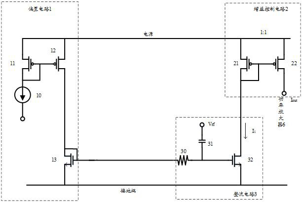
[0070] In the existing power detection circuit, it usually includes a bias circuit 1, a gain control circuit 2 and a rectification circuit 3, such as figure 1 As shown, the bias circuit 1 is connected with the rectification circuit 3, the bias circuit 1 provides a bias voltage for the rectification circuit 3, the rectification circuit 3 is connected with the gain control circuit 2, and the gain control circuit 2 is used for the first output of the rectification circuit 3 A current is am...


PUM


Abstract

The embodiments of the present application disclose a power detection circuit and method for a power amplifier. The power detection circuit includes: a bias circuit, a rectifier circuit, a DC offset circuit, an offset compensation circuit and a gain control circuit; a bias circuit, a rectifier circuit and a DC circuit The cancellation circuits are respectively connected, the DC cancellation circuit is respectively connected with the offset compensation circuit and the rectification circuit, and the gain control circuit is respectively connected with the rectification circuit and the power amplifier.

Description

technical field [0001] The embodiments of the present application relate to the technical field of power amplifier detection, and in particular to a power detection circuit and method of a power amplifier. Background technique [0002] Modern communication systems use more and more complex modulation methods, making the linearity performance requirements of radiofrequency power amplifiers (radiofrequency power amplifiers, RF PAs) higher and higher. In order to ensure the efficiency of PAs and improve the linearity performance of power amplifiers is an urgent problem to be solved. [0003] The existing power detection circuit used in wireless communication system to realize linear bias is usually composed of bias circuit, gain control circuit and rectification circuit, such as figure 1 As shown, when there is a radio frequency signal input, the radio frequency signal is converted into a DC current through the rectification circuit, and the current output by the rectification...

Claims


Application Information

Patent Timeline
Patent Type & Authority Patents(China)
IPC IPC(8): H03F3/24G01R21/00H03F1/00
CPCG01R21/00H03F1/00H03F3/245
Inventor 彭振飞苏强刘传兵
Owner GUANGZHOU HUIZHI MICROELECTRONICS
Why Eureka
Try Eureka