Cooling fin mounting device

A technology for installing devices and heat sinks, which is applied in the direction of modification through conduction heat transfer, cooling/ventilation/heating transformation, electrical components, etc., which can solve problems such as PCB heat sink component damage, so as to solve component damage and avoid pain Discomfort, guaranteed precision effect

Active Publication Date: 2021-03-19
SUZHOU LANGCHAO INTELLIGENT TECH CO LTD
View PDF4 Cites 0 Cited by
  • Summary
  • Abstract
  • Description
  • Claims
  • Application Information

AI Technical Summary

Problems solved by technology

[0005] The purpose of the present invention is to provide a heat sink installation device to solve the technical problem that the existing PCB heat sink installation process easily causes damage to components

Method used


Image

  • Cooling fin mounting device
  • Cooling fin mounting device
  • Cooling fin mounting device

Examples


Embodiment 1

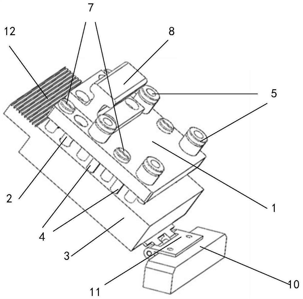
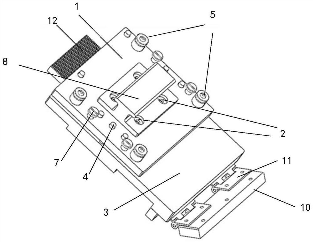
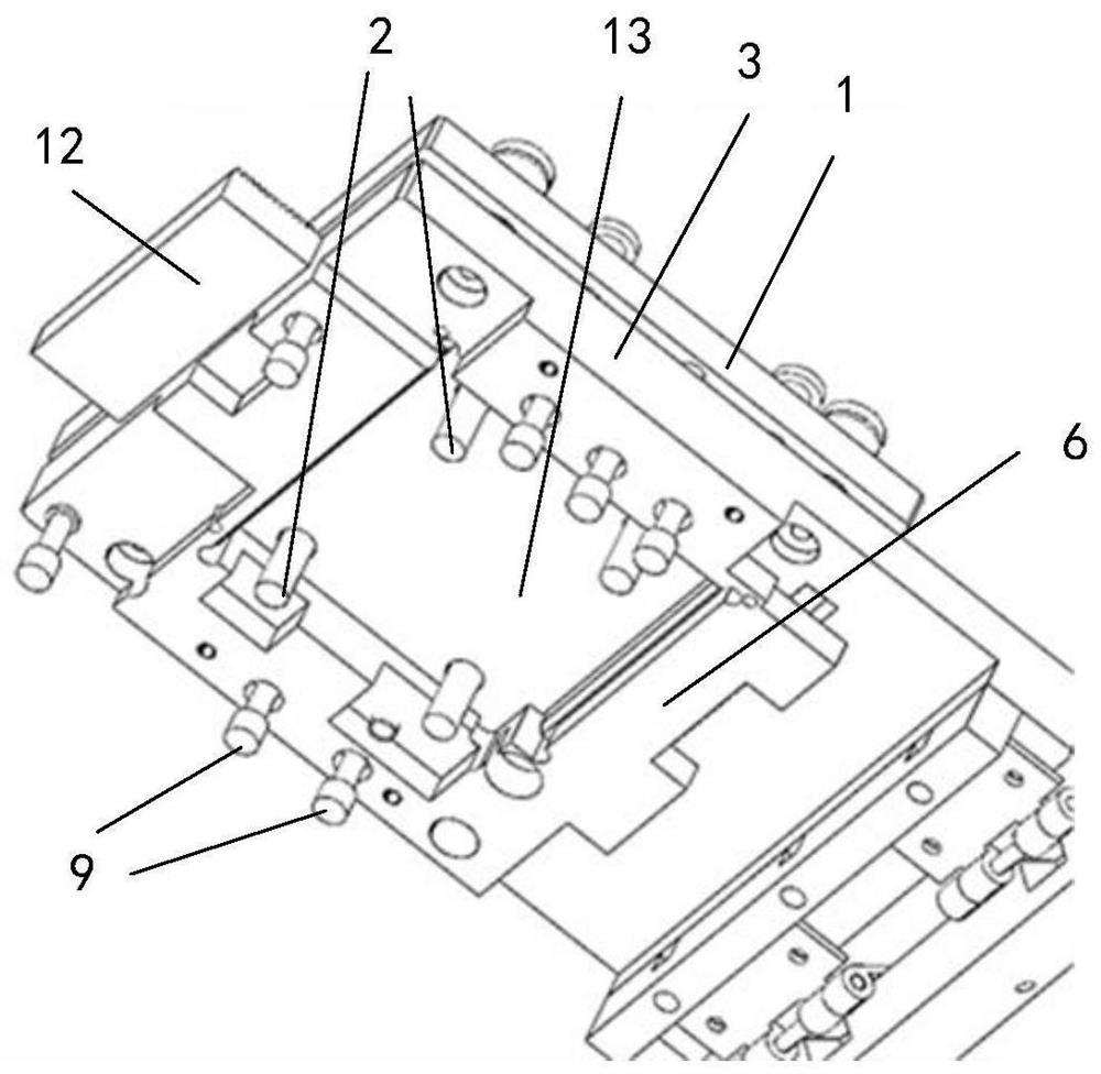
[0033] The heat sink mounting device provided by the embodiment of the present invention is used to install the heat sink 14 of the PCB, such as Figure 4 and Figure 5 As shown, there are two types of heat sinks, one is a heat sink with two fixed plugs, and the other is a heat sink with four fixed plugs. Such as Figure 1 to Figure 3 As shown, the cooling fin installation device includes a pressing plate 1 , a pressing column 2 , a bin plate 3 , a spring 4 and a bearing 5 . in, figure 1 It is a heat sink mounting device with 2 fixed plugs, figure 2 and image 3 It is a heat sink mounting device with 4 fixed plugs. Pressing plate 1 and silo plate 3 are flexibly connected through spring 4 and bearing 5, and the relative distance between pressing plate 1 and silo plate 3 can be changed through compression and rebound of spring 4. The setting of bearing 5 ensures that Smooth and fluid linear motion. The pressing plate 1 is provided with a plurality of pressing columns 2, ...


PUM


Abstract

The invention provides a cooling fin mounting device, belongs to the technical field of mainboard production, and aims to solve the technical problem that components are easily damaged in the mountingprocess of an existing PCB cooling fin. The cooling fin mounting device is used for installing cooling fins of a PCB and comprises a pressing plate, a pressing column, a stock bin plate, a spring anda bearing. The pressing plate is movably connected with the stock bin plate through the spring and the bearing, and the relative distance between the pressing plate and the stock bin plate can be changed through compression resilience of the spring. The pressing plate is provided with a plurality of pressing columns, and the stock bin plate is provided with through holes corresponding to the pressing columns. The stock bin plate is provided with a stock bin for containing cooling fins, and the positions of the multiple pressing columns correspond to the positions of fixed plugs of the coolingfins in the stock bin.

Description

technical field [0001] The invention relates to the technical field of motherboard production, in particular to a cooling fin installation device. Background technique [0002] With the development of electronic information technology, the demand for production of servers and computers is gradually increasing. In the production process, there is generally a process of installing a heat sink on a printed circuit board (PCB for short). [0003] The current method of installing the heat sink is to first place the heat sink on the PCB, align the fixed plug of the heat sink with the installation through hole of the PCB, and press the fixed plug of the heat sink with hands or jigs. During the entire installation process, although manual installation is more accurate, it is prone to pain and discomfort when the hands are pressed for a long time. The use of jig installation often leads to the problem of improper installation or position deviation, which often causes damage to comp...

Claims


Application Information

Patent Timeline
IPC IPC(8): H05K7/20
CPCH05K7/2039H05K7/205
Inventor 李加林王瑜时文静陈龙
Owner SUZHOU LANGCHAO INTELLIGENT TECH CO LTD
Why Eureka
Try Eureka