Self-centering guide rod system for a rifle scope turret

A technology for aiming scopes and adjusting buttons, which is applied to aiming devices, telescopes, instruments, etc., can solve problems such as rotation number errors, and achieve the effect of avoiding kinks

Pending Publication Date: 2021-03-19
SHELTERED WINGS INC D B A VORTEX OPTICS
View PDF8 Cites 1 Cited by
  • Summary
  • Abstract
  • Description
  • Claims
  • Application Information

AI Technical Summary

Problems solved by technology

While this can be a problem when making fine adjustments, it can be of greater concern when the user has to make large changes involving several turns of the knob, which can lead to errors in the number of turns produced

Method used


Image

  • Self-centering guide rod system for a rifle scope turret
  • Self-centering guide rod system for a rifle scope turret
  • Self-centering guide rod system for a rifle scope turret

Examples


Embodiment Construction

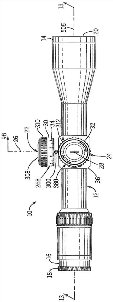
[0060] An embodiment of a rifle scope having a helical cam mechanism is shown, generally indicated by reference numeral 10 .

[0061] figure 1 One embodiment of an improved sighting device is shown, such as a rifle scope 10 with a helical cam mechanism. More specifically, the rifle scope or sighting device 10 has a body 12, in the illustrated embodiment a scope body, which encloses a movable optical element 248 (eg, Figure 13 ), the movable optical element 248 is an erector tube. The scope body is an elongated tube with a larger opening at its front 14 and a smaller opening at its rear 16 . The eyepiece 18 is attached to the rear of the scope body and the objective lens 20 is attached to the front of the scope body. The central axis of the movable optical element defines the optical axis 506 of the rifle scope.

[0062] Elevation adjustment knob 22 and windage adjustment knob 24 are two dials on the outer central portion of scope body 12 . They are incrementally marked o...


PUM


Abstract

An optic device turret for adjusting the optical element of the optic device. A spiral cam mechanism is engaged with the turret to define a maximum and minimum adjustment of the optical element. A rotation indicator displays the amount a knob has been rotated.

Description

[0001] Cross References to Related Applications [0002] This application is a non-provisional application of and claims priority to US Provisional Patent Application No. 62 / 682,502, filed June 8, 2018, which is hereby incorporated by reference in its entirety. technical field [0003] The present disclosure relates generally to the field of optical sighting devices. More specifically, the present disclosure relates to apparatus and methods for conveniently adjusting such optics. Background technique [0004] The adjustment knob is one of two controls on the outer center portion of the riflescope body. The knobs are labeled in increments and are used to adjust elevation and windage to change the hit point. Conventional adjustment knobs have indicia that indicate how many click adjustments have been toggled on the adjustment knob, or angular offset or distance compensation for a given magazine. A click is a tactile adjustment increment on the scope's windage or elevation a...

Claims


Application Information

Patent Timeline
Patent Type & Authority Applications(China)
IPC IPC(8): F41G11/00G02B7/02G02B23/14G02B23/16
CPCF41G1/38G02B7/023G02B7/004G02B23/16
Inventor 塞缪尔·J·哈密尔顿
Owner SHELTERED WINGS INC D B A VORTEX OPTICS
Why Eureka
Try Eureka