Piston type water spraying mop bucket

A mop bucket and piston-type technology, which is applied in the field of piston-type water spray mop buckets, can solve the problems of restricting the placement of mop buckets, inconvenience, and inability to move anywhere

Pending Publication Date: 2021-03-23
HEBEI JIESHIBAO DAILY PLASTIC PROD CO LTD
View PDF0 Cites 2 Cited by
  • Summary
  • Abstract
  • Description
  • Claims
  • Application Information

AI Technical Summary

Problems solved by technology

[0003] With immersion cleaning, the water will become dirty after one or two cleanings, and the water needs to be changed frequently, and the cleaning and dehydration of the mop are all performed in the same bucket, so it is very inconvenient to use immersion cleaning; It is very inconvenient to place it in such a way that it cannot be moved anywhere

Method used


Image

  • Piston type water spraying mop bucket
  • Piston type water spraying mop bucket
  • Piston type water spraying mop bucket

Examples


Embodiment 1

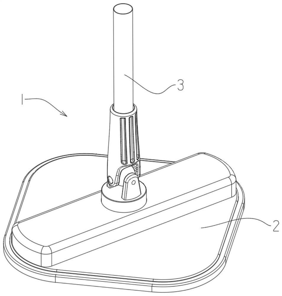
[0060] A spin mop, such as figure 1 As shown: the mop 1 includes a mop head 2 and a mop rod 3, the mop head can be rotated to realize cleaning and / or dehydration, and the rotation of the mop head is driven by hand pressing the mop rod or a motor;

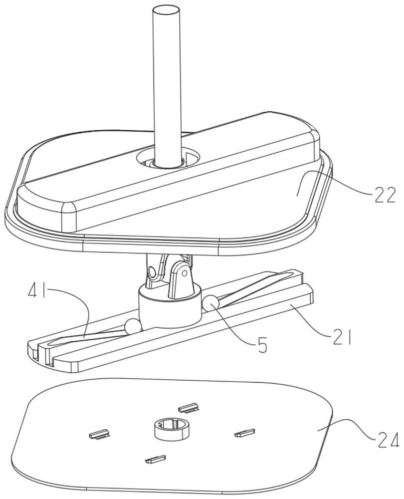
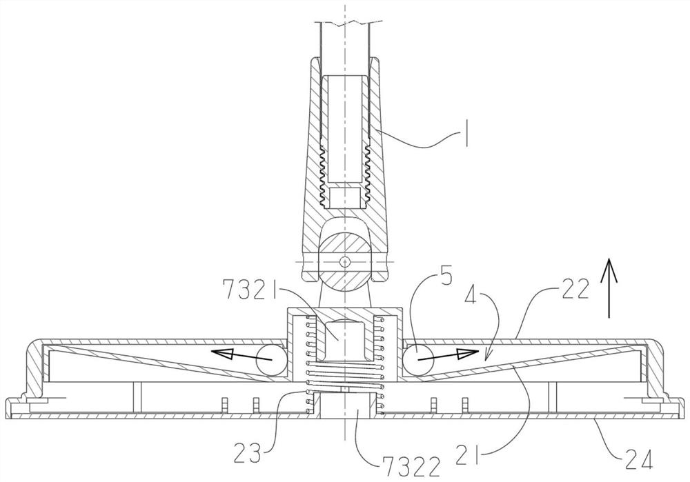
[0061] Such as Figures 2 to 4 As shown in the figure: the mop head includes a fixed plate 21 and a lifting plate 22, the fixed plate is connected to the mop rod and can rotate, the lifting plate is connected to the fixed plate, and the lifting plate is relatively The fixed plate can move up and down, and the lifting plate can rotate with the fixed plate, and the wiper is fixedly connected to the lifting plate. It should be noted that the lifting plate mentioned here moves up and down relative to the mop head. time status.

[0062]There is a gap 4 between the lifting plate and the fixed plate, and the gap gradually decreases from the center of the lifting plate to the outer periphery, and a driving member 5 is arranged in the gap,...

Embodiment 2

[0092] The difference between this embodiment and embodiment 1 is the structure of the mop bucket;

[0093] This example Figure 12 As shown: the mop bucket includes a barrel body 67, and the mop bucket is provided with a support column 66 for supporting the work of the mop. When in use, put an appropriate amount of water in the mop bucket. When rotating, the wipes can touch the water surface, which is spin cleaning at this time, and after the lifting plate is raised by accelerating the rotating speed of the mop, the wipes leave the water surface, which is spin dehydration at this time.

[0094] In this example, if Figure 13 As shown: the barrel body is also provided with a cleaning brush 68, and when the mop is at a low position for cleaning, the cleaning brush can scrub the surface of the mop to be wiped.

Embodiment 3

[0096] The difference between this embodiment and Embodiment 1 lies in the structure of the driving part on the mop and the structure of the gap matched with the driving part;

[0097] Such as Figure 14 to Figure 17 As shown: in this embodiment, the height gradient gap is realized by the inclined surface provided on the lifting plate, and the driving part is in the shape of a rectangular block as a whole, and the driving part also has an inclined surface 54 that matches the inclined surface on the lifting plate;

[0098]The driving part of the sphere is mainly rolling, and may also be accompanied by sliding action. When the sphere structure is adopted, the sensitivity of the lifting plate is high, that is, it can move without a high speed to realize the driving and lifting; the block-shaped The driving part is sliding, and due to the influence of friction, the speed required for its movement will be relatively high; there are actually no advantages or disadvantages between th...


PUM


Abstract

The invention discloses a piston type water spraying mop bucket, which is internally provided with a piston pump (77) and a supporting part used for supporting a mop to rotate, the supporting part canrotate along with a mop head, and the piston pump is driven by rotation of the supporting part. The piston pump works to pump out water in the mop bucket and spray the water on a wiping object of themop so as to finish washing. The piston pump is driven to work by manually pressing the rotary mop or electrically rotating the mop, clear water in the bucket is pumped out and sprayed to the mop through the water pump, the cleaning effect of the mop is improved, and the mop bucket does not need to be connected with a water source and can be placed at will in use.

Description

technical field [0001] The invention belongs to the technical field of cleaning products, in particular to a piston-type water spray mop bucket. Background technique [0002] The mop and the matching mop bucket are commonly used combined cleaning tools. The mop needs clear water to cooperate with rinsing to clean it up. water; [0003] With immersion cleaning, the water will become dirty after one or two cleanings, and the water needs to be changed frequently. Moreover, the cleaning and dehydration of the mop are all performed in the same bucket, so it is very inconvenient to use immersion cleaning; It is also very inconvenient to place it in a position where it cannot be moved anywhere. Contents of the invention [0004] The technical problem mainly solved by the present invention is to provide a piston-type water spray mop bucket, which drives the piston pump to work through the hand-pressed rotary mop or electric rotary mop, and the water pump pumps out the clear wate...

Claims


Application Information

Patent Timeline
IPC IPC(8): A47L13/58
CPCA47L13/58
Inventor 任永旺
Owner HEBEI JIESHIBAO DAILY PLASTIC PROD CO LTD
Why Eureka
Try Eureka