
Underwater releaser and underwater equipment recovery system

A releaser and watertight technology, which is applied in underwater operation equipment, underwater ships, ships, etc., can solve the problems of difficult wireless signal transmission, affecting the recovery of underwater equipment, and long construction period

Pending Publication Date: 2021-03-23
深圳市智慧海洋科技有限公司
View PDF0 Cites 2 Cited by
  • Summary
  • Abstract
  • Description
  • Claims
  • Application Information

AI Technical Summary

Problems solved by technology

However, the existing buoys are mainly based on sea surface observation, and it is difficult to realize seabed observation; the planning and construction period of the seabed observation network is long, and the operation, maintenance and cost are high, especially the recovery of underwater equipment is difficult.
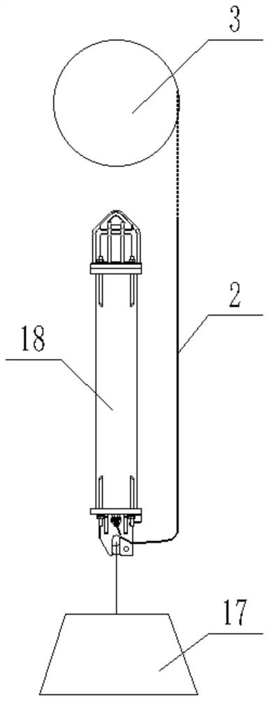
[0003] At present, the recovery of underwater equipment depends on the underwater releaser. The underwater releaser is a commonly used auxiliary equipment for underwater equipment recovery in marine observation systems; its main function is to unlock the lower mount by receiving external control signals. The hook of the counterweight separates the underwater releaser from the counterweight and then floats the cabin to the water surface by virtue of the buoyancy of the upper buoyancy chamber, thereby achieving the purpose of recovering the test equipment in the buoyancy chamber; at present, the existing underwater releaser Most of them use wireless methods to receive external control signals, but due to the changeable marine environment, it is often difficult to transmit wireless signals, resulting in the inability to unlock the hook in time, resulting in the failure of the underwater releaser and the counterweight to disengage normally , which seriously affects the recovery of underwater equipment

Method used


Image

  • Underwater releaser and underwater equipment recovery system
  • Underwater releaser and underwater equipment recovery system
  • Underwater releaser and underwater equipment recovery system

Examples


Embodiment Construction

[0026] In order to make the purpose, technical solutions and advantages of the embodiments of the present invention clearer, the technical solutions in the embodiments of the present invention will be clearly and completely described below in conjunction with the drawings in the embodiments of the present invention. Obviously, the described embodiments It is a part of embodiments of the present invention, but not all embodiments. Based on the embodiments of the present invention, all other embodiments obtained by persons of ordinary skill in the art without making creative efforts belong to the protection scope of the present invention.

[0027] Below in conjunction with accompanying drawing and specific embodiment the present invention is described in further detail:

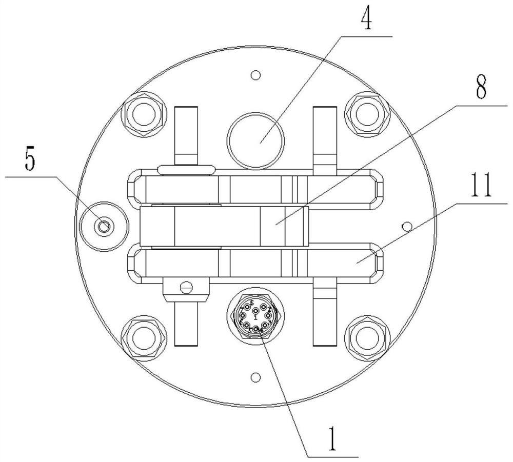
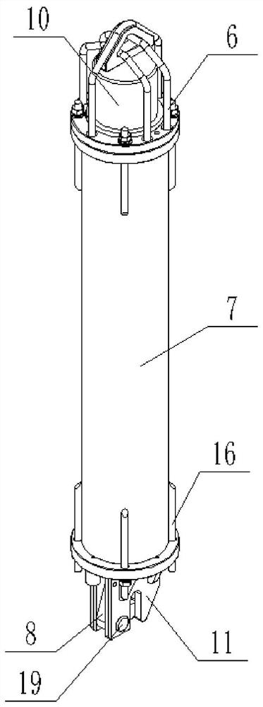
[0028] Such as Figure 1-Figure 5 As shown, the first aspect of the present application provides an underwater release device, which includes: a body with a watertight socket 1; the watertight socket 1 is used...


PUM


Abstract

The invention relates to the technical field of underwater equipment, in particular to an underwater releaser and an underwater equipment recovery system. The underwater releaser comprises a body, thebody is provided with a watertight socket, the watertight socket is used for being externally connected with a communication cable so that the body can be electrically connected with a buoyancy compartment, and according to the scheme, on the premise that the mode of receiving external underwater acoustic control signals is reserved, the mode of receiving the external control signals in a wired mode is added; that is to say, electrical connection with the buoyancy compartment is realized through an external communication cable; in conclusion, when underwater acoustic signals are difficult totransmit, signal transmission can be guaranteed in a wired mode, and then it is guaranteed that the hook is unlocked in time, the underwater releaser is normally separated from the balancing weight, and underwater equipment recovery is smoothly completed.

Description

technical field [0001] The invention relates to the technical field of underwater equipment, in particular to an underwater releaser and an underwater equipment recovery system. Background technique [0002] With the development of marine hydrological monitoring and seabed observation network technology, people have more and more understanding of marine ecology. However, the existing buoys mainly focus on sea surface observation, and it is difficult to realize submarine observation; the planning and construction period of the submarine observation network is long, and the operation, maintenance and cost are high, especially the recovery of underwater equipment is difficult. [0003] At present, the recovery of underwater equipment depends on the underwater releaser. The underwater releaser is a commonly used auxiliary equipment for underwater equipment recovery in marine observation systems; its main function is to unlock the lower mount by receiving external control signals...

Claims


Application Information

Patent Timeline
IPC IPC(8): B63C11/34B63G8/00B63G8/24
CPCB63C11/34B63G8/001B63G8/24B63G2008/007
Inventor 赵晓飞国婧倩支登峰刘金山
Owner 深圳市智慧海洋科技有限公司
Learn More