A Constant Tension Control Mechanism for Warp Knitting Machine Convenient to Fix at Both Ends

A technology of constant tension and control mechanism, applied in warp knitting, textiles, papermaking, knitting, etc., can solve the problems of adjusting the installation posture, inconvenient disassembly and positioning, inconvenience, etc., and achieve the effect of preventing accidental touch, quick cleaning, and quick disassembly

Active Publication Date: 2022-02-08
浙江省嵊州市绿园塑料网业有限公司
View PDF0 Cites 0 Cited by
  • Summary
  • Abstract
  • Description
  • Claims
  • Application Information

AI Technical Summary

Problems solved by technology

[0005] The purpose of the present invention is to provide a constant tension control mechanism for warp knitting machines that is convenient for fixing both ends, so as to solve the problems in the above-mentioned background technology that it is not easy to clean and maintain, it is not convenient to adjust the installation posture and it is not convenient to disassemble and position

Method used


Image

  • A Constant Tension Control Mechanism for Warp Knitting Machine Convenient to Fix at Both Ends
  • A Constant Tension Control Mechanism for Warp Knitting Machine Convenient to Fix at Both Ends
  • A Constant Tension Control Mechanism for Warp Knitting Machine Convenient to Fix at Both Ends

Examples


Embodiment Construction

[0027] Next, the technical solutions in the embodiments of the present invention will be described in connection with the drawings of the embodiments of the present invention, and it is understood that the described embodiments are merely the embodiments of the present invention, not all of the embodiments. Based on the embodiments of the present invention, all other embodiments obtained by those of ordinary skill in the art are in the range of the present invention without making creative labor premise.

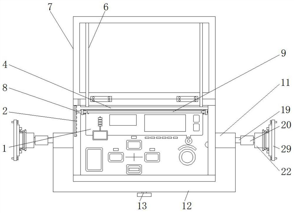
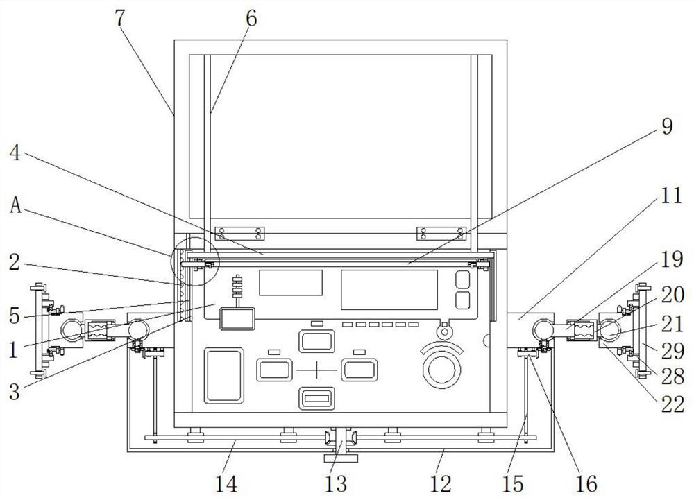
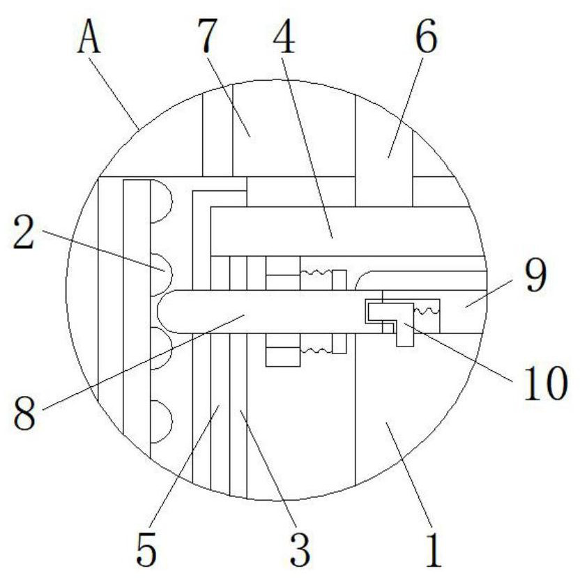
[0028] See Figure 1-6 The present invention provides a technical solution: a convenient fixed two warp knitting machine constant tension control mechanism, the tension controller comprises a main body 1, the fixing block 2, the vertical grooves 3, the movable lever 4, the elastic cord (5), fixed rope 6, protective cover 7, the lever 8 function, mounting bar 9, stripper bar 10, the first fixed cylinder 11, the stationary housing 12, the operation lever 13, the connecting rod 14, ...


PUM


Abstract

The invention belongs to the technical field of warp knitting machine constant tension control, in particular to a warp knitting machine constant tension control mechanism conveniently fixed at both ends, comprising a tension controller body and a first fixing cylinder, the left side of the tension controller body is fixed with a As for the fixed block, the lower end of the movable rod is fixed with an elastic pull cord, and the first fixed cylinder is fixed on both sides of the tension controller body. The constant tension control mechanism of the warp knitting machine, which is conveniently fixed at both ends, pulls the protective cover downward, and the protective cover and the outer side of the tension controller body fit together, so as to block the dust on the outer side of the tension controller body and prevent the tension controller body from Inadvertent touch, the elastic pull rope pulls the movable rod and the cross bar to move downward inside the vertical groove, the fixed block squeezes the end of the cross bar, and the cross bar drives the installation rod to reciprocate to clean the outer wall of the tension controller body to realize tension control. Quick cleaning of the controller body, by pulling the cleaning rod horizontally, the installation and replacement of the installation rod and brush can be realized.

Description

Technical field [0001] The present invention relates to a warp knitting machine constant tension control technology, specifically to a convenient fixed two warp knitting machine constant tension control mechanism. Background technique [0002] Warp knitting machine is a yarn material arranged in parallel to form a knitted automated production equipment, by using a warp knitting machine, fast warp yarn in warp knitting machine process, often need to meet constant feed tension of the tension control mechanism to adjust the transmission process. [0003] After a conventional warp knitting machine constant tension control device mounting structure is fixed, the process is easy to use the device panel dust buildup, repeated manual Qing Li is inconvenient, and there is a device on the operation panel easily lead to inadvertently exposed to the outside, the installation is completed and the device , not easy to use in accordance with demand for flexible mounting position adjusting devic...

Claims


Application Information

Patent Timeline
Patent Type & Authority Patents(China)
IPC IPC(8): D04B27/14D04B35/32
CPCD04B27/14D04B35/32
Inventor 陈传标
Owner 浙江省嵊州市绿园塑料网业有限公司
Why Eureka
Try Eureka