
Anti-icing water tank structure

An anti-icing and water tank technology, applied in water heaters, fluid heaters, lighting and heating equipment, etc., can solve the problems of low heat utilization rate, inability to heat and antifreeze, etc., achieve high heat utilization rate, novel structure, Effect of avoiding ice damage

Active Publication Date: 2021-03-26
广德君安达消防科技有限公司
View PDF6 Cites 0 Cited by
  • Summary
  • Abstract
  • Description
  • Claims
  • Application Information

AI Technical Summary

Problems solved by technology

[0006] However, the structure of the water tank in the above-mentioned anti-freezing method is simple, and it can only anti-freeze the water tank, and the heat utilization rate is low, and it is impossible to heat and anti-freeze other devices connected to the water tank.

Method used


Image

  • Anti-icing water tank structure
  • Anti-icing water tank structure

Examples


Embodiment 1

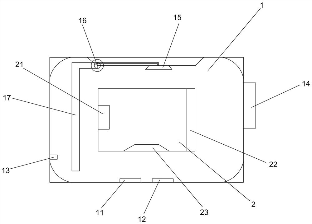
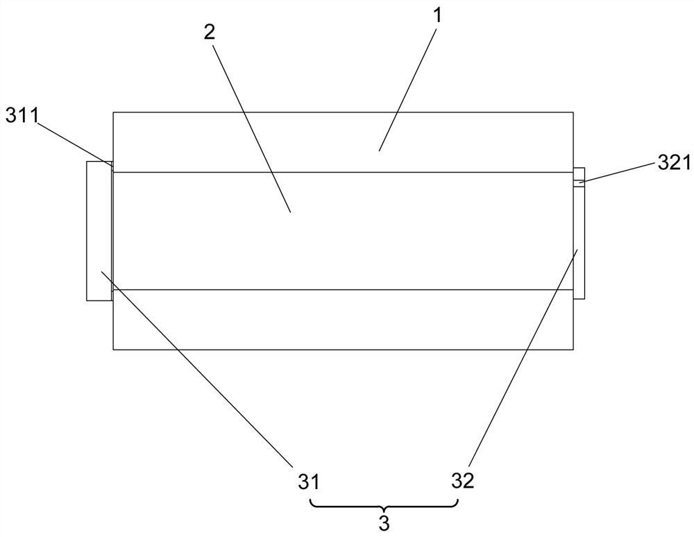
[0029] Embodiment one: if figure 1 , 2 As shown, it is only one of the embodiments of the present invention, an anti-freezing water tank structure, including a back-shaped water tank 1 and an accommodating chamber 2 arranged in the middle of the back-shaped water tank 1, and the inner side of the back-shaped water tank 1 A temperature sensor 11 and a heating device 12 are arranged at the bottom, and a reel 21 for accommodating a water spray pipe, a mounting plate 22 for accommodating a booster pump, and a mounting plate for installing a medicament mixing device are arranged in the accommodating cavity 2 . Mounting seat 23, the inner wall of the back-shaped water tank 1 is provided with a liquid level sensor 13, the outer side of the back-shaped water tank 1 is provided with a display screen 14, the end of the accommodating cavity 2 is provided with a cover 3, the temperature The sensor 11 , the heating device 12 and the liquid level sensor 13 are all electrically connected to...

Embodiment 2

[0038] Embodiment two, still as figure 1 , 2As shown, it is only one of the embodiments of the present invention. On the basis of Embodiment 1, in an anti-freezing water tank structure of the present invention, the top of the back-shaped water tank 1 is provided with a spray head 15, which communicates with the spray head 15 A water pump 16 and a water suction pipe 17 communicating with the water pump 16, the end of the water suction pipe 17 away from the water pump 16 extends toward the bottom of the back-shaped water tank 1 . When the water pump 16 was turned on, the water at the bottom of the zigzag water tank 1 was pumped through the water suction pipe 17, and sprayed from the nozzle 15 nozzles provided on the top of the zigzag water tank 1 to make the water in the zigzag water tank 1 flow, so that the zigzag water tank 1 Water temperature zone balance.

[0039] Here, there are three situations: 1. The water level in the back-shaped water tank 1 is lower than the height ...


PUM


Abstract

The invention provides an anti-icing water tank structure, and relates to the technical field of fire-fighting equipment. The anti-icing water tank structure comprises a concentric-square-shaped watertank and a containing cavity arranged in the middle of the concentric-square-shaped water tank, a temperature sensor and a heating device are arranged at the bottom of the inner side of the concentric-square-shaped water tank. A reel used for containing a water spraying pipe, a mounting plate used for containing a booster pump and a mounting base used for mounting a medicament mixing device are arranged in the containing cavity. A liquid level sensor is arranged on the inner side wall of the concentric-square-shaped water tank, a display screen is arranged on the outer side of the concentric-square-shaped water tank, and a sealing cover is arranged at the end of the containing cavity. And the temperature sensor, the heating device and the liquid level sensor are all electrically connectedwith the display screen. The anti-icing water tank structure is novel in structure and high in heat utilization rate, other devices connected with the water tank are prevented from icing and being damaged under the condition that the water tank is in an anti-freezing state, the temperature in the water tank is controllable and visible, and the anti-icing water tank structure can be additionally arranged in any fire fighting truck.

Description

technical field [0001] The invention relates to the technical field of fire fighting equipment, [0002] In particular, the present invention relates to an anti-freezing water tank structure. Background technique [0003] Fire trucks, also known as fire trucks, refer to special vehicles that are mainly used to perform fire response tasks. Fire departments in most countries, including China, also use them for other emergency rescue purposes. Fire trucks can transport firefighters to the scene of disasters and provide them with a variety of tools for disaster relief tasks. [0004] Modern fire trucks are usually equipped with steel ladders, water guns, portable fire extinguishers, self-contained breathing apparatus, protective clothing, rescue tools, first aid tools and other equipment, and some of them are also equipped with large fire extinguishing equipment such as water tanks, water pumps, and foam fire extinguishing devices. The appearance of fire trucks in most areas i...

Claims


Application Information

Patent Timeline
IPC IPC(8): A62C31/00A62C31/28A62C37/00F24H1/20
CPCA62C31/00A62C31/005A62C31/28A62C37/00F24H1/202
Inventor 蔚军
Owner 广德君安达消防科技有限公司
Learn More