Die steel hoisting and clamping device

A die steel and hoisting technology, applied in the direction of hoisting device, lifting frame, etc., can solve the problems of fixed transportation position, unsuitable for large-scale promotion and use, and inability to use flexibly, so as to improve hoisting efficiency, work efficiency and general use. Sexual, well-designed effects

Inactive Publication Date: 2021-03-26
浙江三门太和大型锻造有限公司
View PDF10 Cites 0 Cited by
  • Summary
  • Abstract
  • Description
  • Claims
  • Application Information

AI Technical Summary

Problems solved by technology

The quality of the mold directly affects the quality of the pressure processing process, the precision output of the product and the production cost, and the quality and service life of the mold are not only dependent on the reasonable structural design and processing accuracy, but also mainly affected by the mold material and heat treatment. In the transportation and transportation of steel, it is necessary to lift and clamp the mold steel. The transportation position of the traditional lifting device is generally fixed and cannot be used flexibly, so it is not suitable for large-scale promotion and use. Therefore, a flexible clamping and transmission device is designed. Die steel hoisting and clamping device is very necessary

Method used


Image

  • Die steel hoisting and clamping device
  • Die steel hoisting and clamping device
  • Die steel hoisting and clamping device

Examples


Embodiment 1

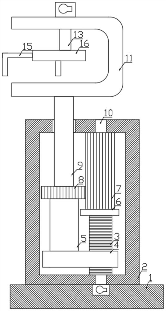
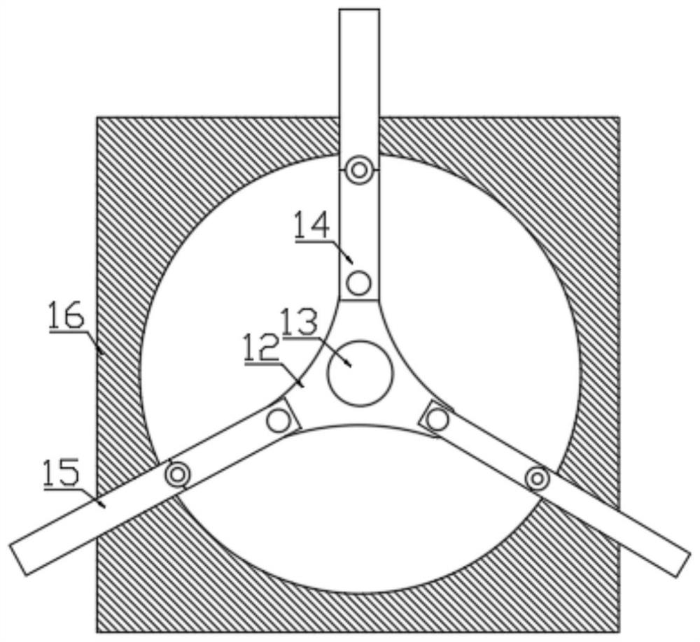
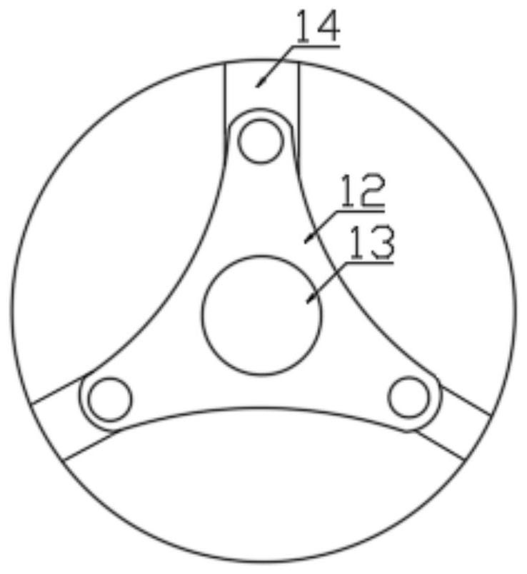
[0021] Example 1: Please refer to Figure 1~4 , in an embodiment of the present invention, a mold steel hoisting and clamping device includes a base 1, a device box 2 is fixedly arranged on the upper side of the base 1 and a driving shaft 10 is arranged on the right side of the inside of the device box 2, and the outer side of the lower end of the driving shaft 10 is fixedly installed There is a leading screw 3 and the outer side of the leading screw 3 is equipped with a sliding sleeve 4, the outer side of the upper end of the driving shaft 10 is fixedly provided with a driving wheel 7 and the left side of the driving wheel 7 is equipped with a driven wheel 8, and the upper end of the sliding sleeve 4 is fixedly connected to the push rod 5 and The upper end of the pushing rod 5 is slidingly connected to the driven wheel 8, the upper end of the driven wheel 8 is fixedly connected to the moving rod 9 and the upper end of the moving rod 9 is fixedly connected to the clamping frame...

Embodiment 2

[0022] Embodiment 2: The invention also provides another embodiment, which is improved on the basis of the above embodiment. The inside of the clamping rod 15 is provided with an anti-slip layer to prevent the die steel from being clamped during the clamping process. slide.

[0023] The working principle of the present invention: start the motor to rotate the driving shaft 10 connected to it, the driving shaft 10 drives the screw 3 and the driving wheel 7 fixedly installed with it to rotate, and the rotation of the leading screw 3 drives the sliding sleeve 4 installed with it to carry out Moving vertically up and down, the sliding sleeve 4 drives the pushing rod 5 fixedly connected with it to move vertically up and down, and the pushing rod 5 drives the driven wheel 8 which is slidingly connected with it to move up and down, and then the clamping frame 11 is moved up and down through the moving rod 9 For height adjustment, the driving wheel 7 rotates to drive the driven wheel ...


PUM


Abstract

The invention discloses a die steel hoisting and clamping device and relates to the mechanical field. The die steel hoisting and clamping device comprises a base, wherein a device box is fixedly arranged on the upper side of the base, a driving shaft is arranged on the right side in the device box, a lead screw is fixedly installed on the outer side of the lower end of the driving shaft, a slidingsleeve is installed on the outer side of the lead screw in a matched mode, a driving wheel is fixedly arranged outside the upper end of the driving shaft, the left side of the driving wheel is provided with a driven wheel in a matched manner, the upper end of the sliding sleeve is fixedly connected with a pushing rod, the upper end of the pushing rod is connected with the driven wheel in a sliding mode, the upper end of the driven wheel is fixedly connected with a moving rod, and the upper end of the moving rod is fixedly connected with a clamping frame. A device plate is arranged in the clamping frame, a rotating plate is arranged in the device plate, rotating rods are evenly arranged on the rotating plate, the other ends of the rotating rods are connected with clamping rods, and the upper end of the rotating plate is provided with a rotating shaft. The die steel hoisting and clamping device is reasonable in design and achieves the work of rotating and vertically camping die steel atdifferent positions, moreover, die steel of different sizes can be clamped and fixed, and the working efficiency and universality of the die steel hoisting and clamping device are improved.

Description

technical field [0001] The invention relates to the field of machinery, in particular to a mold steel hoisting and clamping device. Background technique [0002] Die steel is a type of steel used to make molds such as cold stamping dies, hot forging dies, and die-casting dies. Mold is the main processing tool for manufacturing parts in industrial sectors such as machinery manufacturing, radio instruments, motors, and electrical appliances. The quality of the mold directly affects the quality of the pressure processing process, the precision output of the product and the production cost, and the quality and service life of the mold are not only dependent on the reasonable structural design and processing accuracy, but also mainly affected by the mold material and heat treatment. In the transportation and transportation of steel, it is necessary to lift and clamp the mold steel. The transportation position of the traditional lifting device is generally fixed and cannot be use...

Claims


Application Information

Patent Timeline
IPC IPC(8): B66F7/14B66F7/28
CPCB66F7/14B66F7/28
Inventor 叶君志刘玉娇叶萧藩
Owner 浙江三门太和大型锻造有限公司
Why Eureka
Try Eureka