
Novel radar sensor time-sharing power-saving circuit

A radar sensor and circuit technology, which is applied to circuit devices, DC network circuit devices, instruments, etc., can solve the problems of long shutdown and startup time, waste of power, and large startup delay of the radar.

Pending Publication Date: 2021-03-26
浙江芯力微电子股份有限公司
View PDF0 Cites 0 Cited by
  • Summary
  • Abstract
  • Description
  • Claims
  • Application Information

AI Technical Summary

Problems solved by technology

But the working power consumption of 24GHz is relatively large. In the 5V environment, there is generally a working current of about 50mA
The purpose of saving power can be achieved by letting the radar chip work in time-sharing. However, due to the slow startup time of the radar circuit, it takes a long time for the radar to turn off and start, which cannot meet the needs of power saving.
[0003] During the start-up process of the radar, the op amp and other devices in the intermediate frequency amplifier circuit will bring a large start-up delay, which is the main reason for the slow start-up time. It takes hundreds of milliseconds to reach the stable state of the circuit.
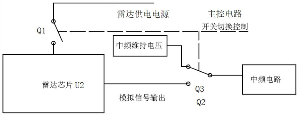
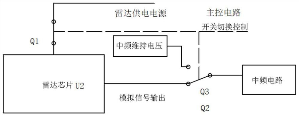
Among them, the most influential is the output voltage of the radar chip. When the radar chip is turned off to on, the signal output will jump from 0 volts to 1.6 volts. This jump will cause the subsequent intermediate frequency amplifier circuit to be completely saturated. Returning to a stable state, the above will cause the radar system to take too long to start, waste power and other problems

Method used


Image

  • Novel radar sensor time-sharing power-saving circuit
  • Novel radar sensor time-sharing power-saving circuit
  • Novel radar sensor time-sharing power-saving circuit

Examples


Embodiment Construction

[0025] The following description serves to disclose the present invention to enable those skilled in the art to carry out the present invention. The preferred embodiments described below are only examples, and those skilled in the art can devise other obvious variations. The basic principles of the present invention defined in the following description can be applied to other embodiments, variations, improvements, equivalents and other technical solutions without departing from the spirit and scope of the present invention.

[0026] In the preferred embodiment of the present invention, those skilled in the art should note that the antennas and resistors involved in the present invention can be regarded as prior art.

[0027] preferred embodiment.

[0028] The invention discloses a new type of time-sharing power-saving circuit for radar sensors, which is used to prevent the radar chip from taking too long to start to save power. It includes a main control circuit, a radar chip...


PUM


Abstract

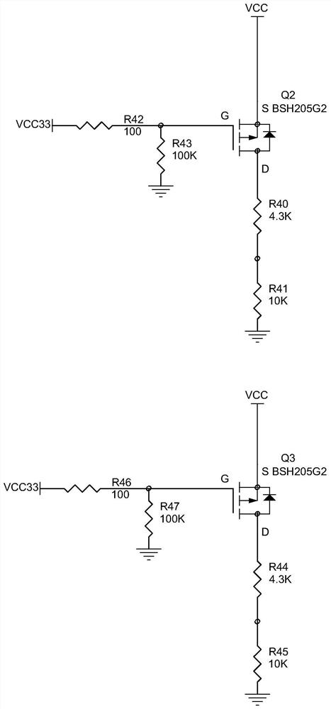
The invention discloses a novel radar sensor time-sharing power-saving circuit which is used for avoiding overlong starting time consumption of a radar chip so as to save power, and the circuit comprises a main control circuit, a radar chip circuit, an intermediate frequency voltage maintaining circuit and an intermediate frequency circuit, the main control circuit is electrically connected with the radar chip circuit and the intermediate frequency circuit respectively; the radar chip circuit is electrically connected with a radar power supply through a first field effect transistor Q1 of themain control circuit, and the radar chip circuit is further electrically connected with the intermediate frequency circuit through a second field effect transistor Q2 and a third field effect transistor Q3 of the intermediate frequency voltage maintaining circuit. According to the novel radar sensor time-sharing power-saving circuit disclosed by the invention, the three MOS transistors are used for respectively controlling the on-off of the power supply of the radar chip and the keeping of the radar output voltage, and different circuit states are switched through an analog switch, so that theoverlong starting time consumption of a radar system is avoided, and the purpose of power saving is achieved.

Description

technical field [0001] The invention belongs to the technical field of time-sharing power saving of radar sensors, and in particular relates to a novel time-sharing power saving circuit of radar sensors. Background technique [0002] The 24GHz radar sensor occupies a certain market in the application of the Internet of Things, and it has many applications in smart home, smart transportation, and smart electrical. However, the working power consumption of 24GHz is relatively large. In a 5V environment, there is generally a working current of about 50mA. The purpose of saving power can be achieved by letting the radar chip work in time-sharing. However, due to the slow startup time of the radar circuit, it takes a long time for the radar to turn off and start, which cannot meet the needs of power saving. [0003] During the start-up process of the radar, the op amp and other devices in the intermediate frequency amplifier circuit will bring a large start-up delay, which is th...

Claims


Application Information

Patent Timeline
Patent Type & Authority Applications(China)
IPC IPC(8): H02J1/00G01S7/02
CPCG01S7/02H02J1/00
Inventor 朱新平卢煜旻朱欣恩
Owner 浙江芯力微电子股份有限公司
Learn More