Posterior chamber phakic intraocular lens

A technology of intraocular lenses and crystals, applied in the direction of intraocular lenses, eye implants, etc., to achieve more resistance, improve rotational stability, and improve axial and radial stability

Pending Publication Date: 2021-03-26
PHYSIOL
View PDF0 Cites 0 Cited by
  • Summary
  • Abstract
  • Description
  • Claims
  • Application Information

AI Technical Summary

Problems solved by technology

[0007] Producing and using several sizes of posterior chamber phakic IOLs based on the anatomy of the patient's eye cannot completely circumvent this defect
In

Method used


Image

  • Posterior chamber phakic intraocular lens
  • Posterior chamber phakic intraocular lens
  • Posterior chamber phakic intraocular lens

Examples


Embodiment Construction

[0110] This section gives a detailed description of the preferred embodiments of the invention. Although specific embodiments are described with reference to the drawings, the present invention is not limited to these embodiments. In particular, the figures or drawings described below are only schematic and are by no means restrictive.

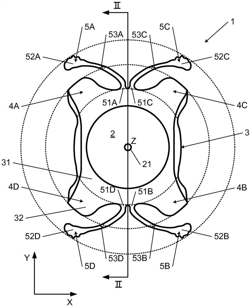
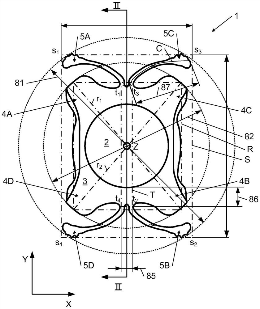
[0111] The geometry represented by the labels X, Y, Z, K, d, R, S, T, C, r1, r2, s1, s2, s3, s4, t1, t2, t3 and t4 is shown in some of the following figures elements, which are purely illustrative to quantify and / or visualize technical characteristics of embodiments of the invention. In particular, these elements are abstract and do not correspond to concrete material objects.

[0112] The present invention provides a posterior chamber type phakic intraocular lens 1, which not only adapts to the anatomical structure of any eye, but also is stable in the axial and radial direction of the optical axis Z in the implantation position of the eye ...


PUM

PropertyMeasurementUnit
Lengthaaaaaaaaaa
Young's modulusaaaaaaaaaa

Abstract

The invention relates to a posterior chamber phakic intraocular lens (1) comprising a central optical part (2), a peripheral haptic part (3) comprising a plurality of support elements (4A-D) arrangedto lie on a ciliary zonule of an eye, and a plurality of flexible elongated haptics (5A-D) arranged to hook into a ciliary sulcus of the eye.

Description

technical field [0001] The present invention relates to an intraocular lens. More specifically, the present invention relates to a posterior chamber phakic intraocular lens. Background technique [0002] In general, phakic intraocular lenses are intraocular lenses that are intended to be placed in the eye to correct vision defects. These intraocular lenses are usually implanted in young patients as a supplement to the lens of the eye. [0003] There are several types of phakic IOLs, of which the posterior chamber type phakic IOLs are intended to be implanted in the region of the eye between the back surface of the iris and the front surface of the lens, and at least partially in the ciliary sulcus of the eye. [0004] The drawback of the implantation of such intraocular lenses lies in the fact that the size of the ciliary sulcus usually varies by a few millimeters from one patient to another based on certain parameters, especially based on the anatomy of the ciliary sulcus...

Claims


Application Information

Patent Timeline
IPC IPC(8): A61F2/16
CPCA61F2/1602A61F2002/1681
Inventor 罗杰·萨尔迪瓦尔克里斯多夫·帕纽利苏亚德·瑞德佐维克
Owner PHYSIOL
Why Eureka
Try Eureka