Disc-type permanent-magnet synchronous motor with combined core stator and bilateral outer rotor
An iron-core stator and iron-core technology, which is applied in the field of combined iron-core stator and double-sided outer rotor disk permanent magnet synchronous motor, can solve the problems of power and torque density gap, increase the axial size of the motor, reduce the force performance index, etc. , to achieve the effect of reducing the amount of winding material, improving the output power and torque index, and improving the efficiency
- Summary
- Abstract
- Description
- Claims
- Application Information
AI Technical Summary
Problems solved by technology
Method used
Image
Examples
Embodiment 1
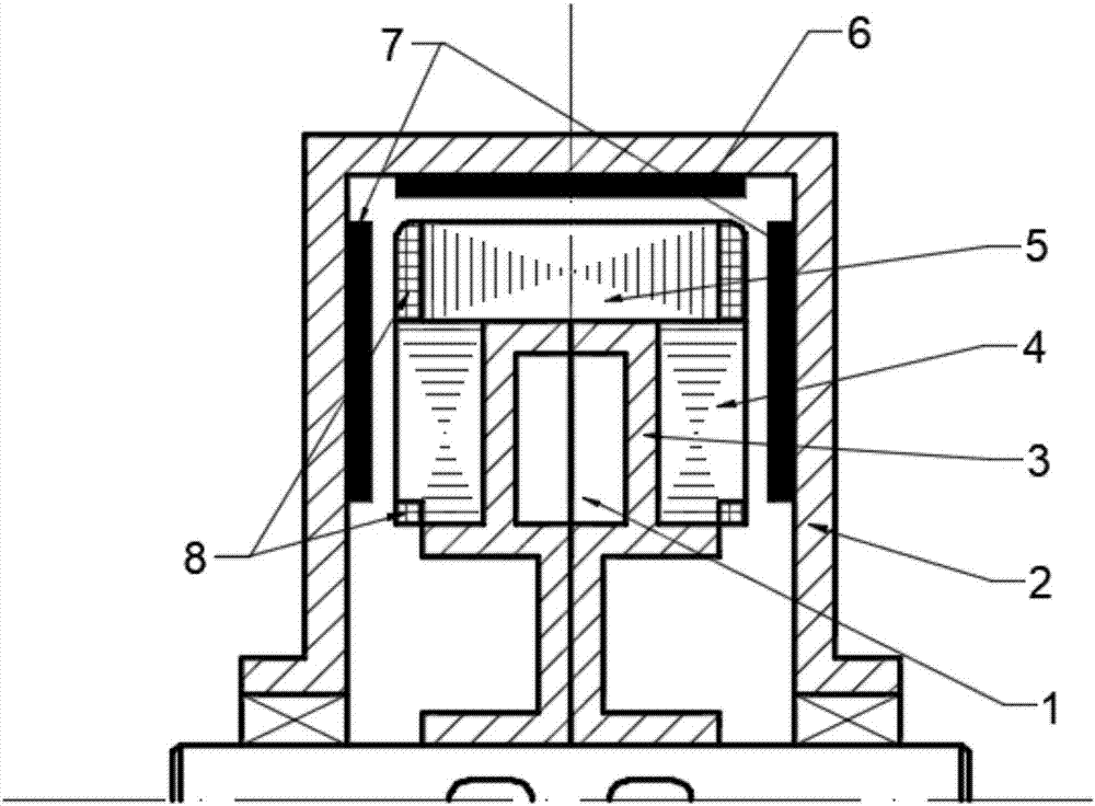
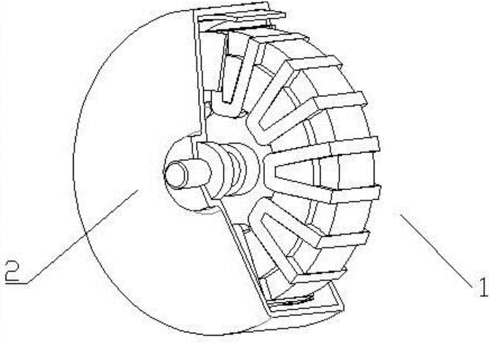
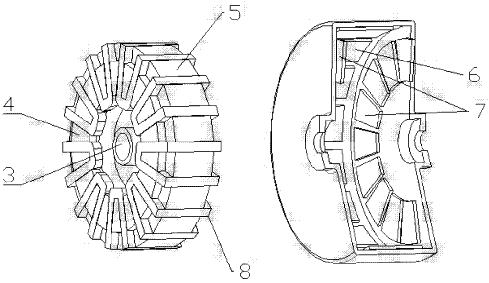
[0036] A combined iron core stator and double-sided outer rotor disc permanent magnet synchronous motor of the present invention, such as Figure 1 to Figure 5 As shown, the stator 1 with a combined iron core and the section with an inverted U-shaped ring (ie figure 1 The cross-section shown in the angle of view) is composed of a double-sided outer rotor 2 of structure. Wherein, the combined iron core stator 1 includes an inner ring iron core 4 and an outer ring iron core 5, and the outer ring surface of the inner ring iron core 4 is embedded in the inner ring surface of the outer ring iron core 5, that is, the inner ring iron core 4 Installed in the through hole of the outer ring iron core 5, the integral combined iron core stator 1 is formed through the connecting piece 3; the combined iron core stator 1 has a continuous winding slot and an embedded same winding coil on its axial ring section 8. On the inner side of the inverted U-shaped ring section structure of the double...
Embodiment 2
[0044] Such as Figure 6 As shown, the winding coil 8 of this embodiment also adopts a centralized winding structure, and its main difference from Embodiment 1 is that the four first winding slots 51 and the three corresponding second winding slots 41 are divided into three The poles are equipped with winding coils 8 . Two first winding parts 81 from different winding coils 8 are installed in each of the first winding slots 51 , and the first winding parts 81 are blocked due to viewing angle, so they are not shown in the figure. Two second winding parts 82 from different winding coils 8 are installed in each second winding slot 41 .
[0045] In other embodiments (not shown), the winding coil 8 may also adopt a distributed winding structure.
[0046] Regardless of centralized winding or distributed winding, according to different stator pole distribution combinations, the assembly relationship between the winding coil 8 and the first winding slot 51 and the second winding slo...
Embodiment 3
[0048] The winding slots on the combined iron core stator 1 can be straight slots, inclined slots or a combination of straight slots and inclined slots. As shown in Figure 7, the difference between this embodiment and Embodiment 1 is that the second winding groove 41 on the inner ring core 4 is an oblique groove, and the first winding groove 51 on the outer ring core 5 is a straight groove . Through the combined form of the winding slot and the parameter design of the slot section, it is easy to improve torque, axial and radial force fluctuations, and improve the dynamic performance of the motor.
PUM
 Abstract
Description
Claims
Application Information
 - R&D
- Intellectual Property
- Life Sciences
- Materials
- Tech Scout
- Unparalleled Data Quality
- Higher Quality Content
- 60% Fewer Hallucinations
Browse by: Latest US Patents, China's latest patents, Technical Efficacy Thesaurus, Application Domain, Technology Topic, Popular Technical Reports.
© 2025 PatSnap. All rights reserved.Legal|Privacy policy|Modern Slavery Act Transparency Statement|Sitemap|About US| Contact US: help@patsnap.com


