
Endoscope snake bone unit, snake bone assembly and endoscope

A technology of endoscope and snake bone, which is applied in the fields of endoscope, medical science, diagnosis, etc., can solve the problems of increasing the difficulty of manufacturing, weak connection strength, low production efficiency, etc., and achieve the reduction of connection parts and high connection strength , the effect of not easy to deform

Pending Publication Date: 2021-03-30
CHONGQING XISHAN SCI & TECH
View PDF0 Cites 1 Cited by
  • Summary
  • Abstract
  • Description
  • Claims
  • Application Information

AI Technical Summary

Problems solved by technology

In the above-mentioned articulation mode, the connection strength between the two snake-bone units is relatively weak, and the precision requirements of the manufacturing and assembly process are high. If there is a slight error in the production process or operation, defects such as deformation and cracking of the snake-bone joints are very likely to occur, affecting internal The normal use of the sight glass; factors such as low production efficiency and high scrap rate also directly lead to high manufacturing costs
Moreover, when the snake bone joint can only realize turning and bending in two directions, or realize bending in four directions, some snake bone unit sections are responsible for bending in the up and down directions, and some snake bone unit sections are responsible for bending in the left and right directions, resulting in a relatively large number of snake bone unit sections. Many, increase the difficulty of manufacturing

Method used


Image

  • Endoscope snake bone unit, snake bone assembly and endoscope
  • Endoscope snake bone unit, snake bone assembly and endoscope
  • Endoscope snake bone unit, snake bone assembly and endoscope

Examples


Embodiment

[0031] In this example, the front and rear orientations, when the endoscope is in use, the side facing the patient is the front, and the side facing away from the patient is the rear.

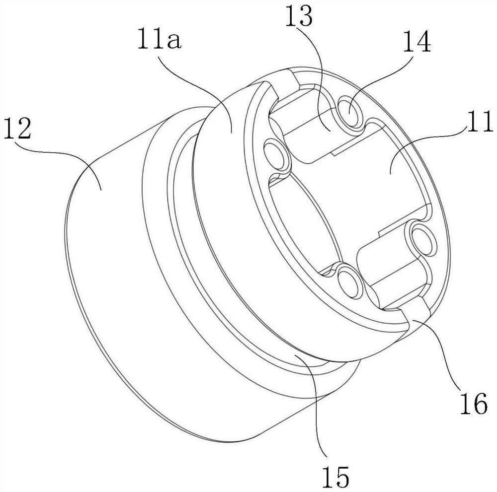
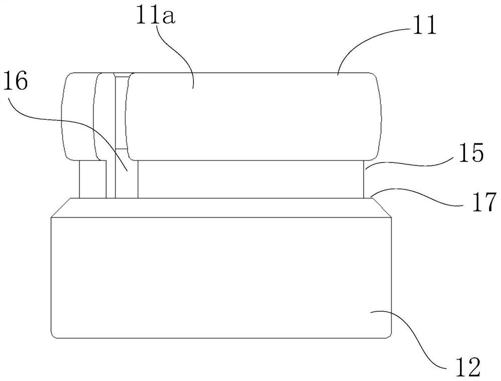
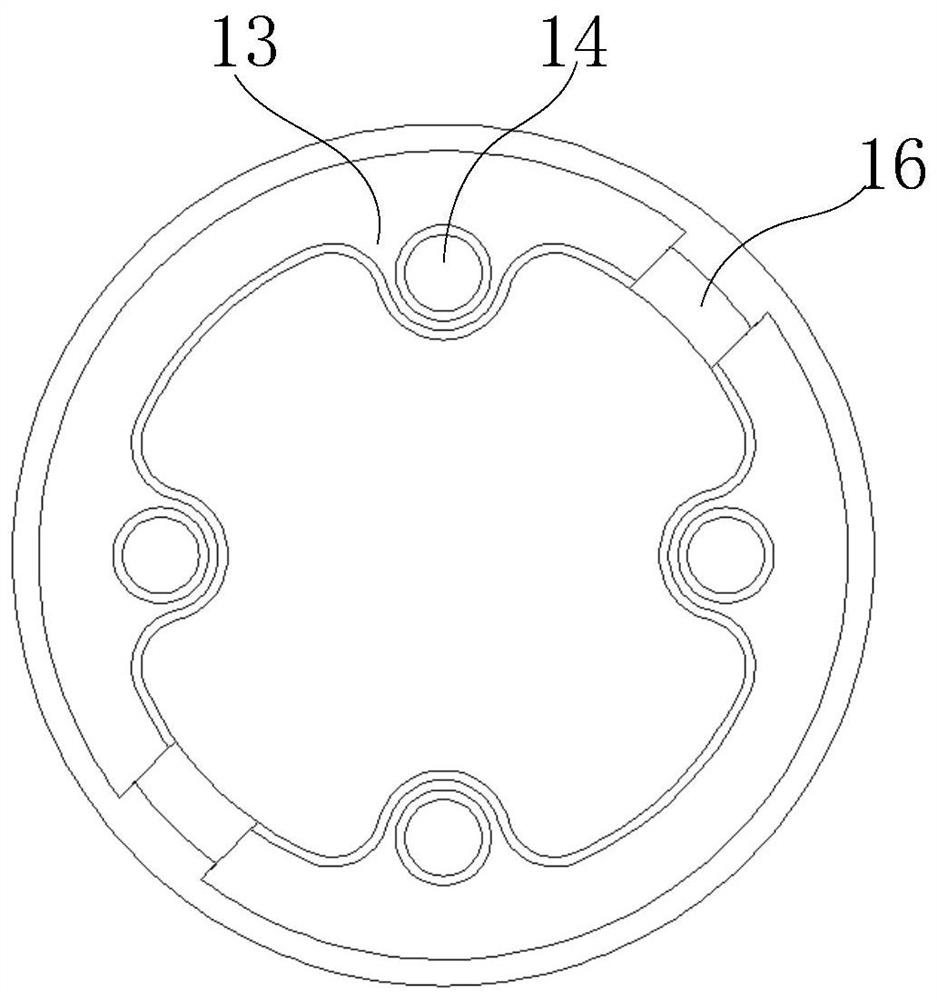
[0032] Such as Figure 1 to Figure 5 As shown, a kind of endoscopic snake bone unit illustrated in this example is used to connect in series to form the bending part of the endoscope; The ends (i.e., the front and rear ends) are respectively the first connection end 11 and the second connection end 12 (or become the first joint and the second joint), wherein the outer wall of the first connection end 11 is provided with a ring of protrusions along the circumferential direction. part 11a, wherein the protruding part 11a is continuous or discontinuous in the circumferential direction; the inner wall of the second connecting end 12 is provided with a circle of concave parts 12a along the circumferential direction, and the size of the concave part 12a is matched with the protruding part 11a, so as ...

Embodiment 1

[0044] The difference of Embodiment 1 is that the protruding part 12c is arranged on the outer wall of the first connecting end 11, and the concave part 11c is arranged on the inner wall of the second connecting end 12, such as Figure 6 As shown, that is, the outer wall of the first connecting end 11 is provided with a concave portion 11c along the circumference, and the inner wall of the second connecting end 12 is provided with a corresponding convex portion 12c as described in the concave portion 11c, and the minimum diameter of the convex portion 12c is Greater than or equal to the minimum outer diameter of the recessed part 11c (that is, the arc radius of the protruding part 12c is greater than or equal to the arc radius of the recessed part 11c), and smaller than the maximum outer diameter of the recessed part 11c, so as to achieve anti-off; the second connecting end 12 is away from One end (rear end) of the first connecting end 11 forms a flaring, and the maximum diamet...

Embodiment 3

[0046] The present invention also provides a snake bone assembly, including at least two endoscopic snake bone units 100 described in Embodiment 1 or Embodiment 2; each snake bone unit 100 is connected in series to form the snake bone assembly, and two adjacent snake bones In the unit 100, the second connecting end 12 of the previous snake-bone unit 100 is sleeved outside the first connecting end 11 of the latter snake-bone unit 100, so that two adjacent snake-bone units 100 can be axially and circumferentially Relatively rotate, and through the cooperation of the concave part and the convex part, two adjacent snake bone units 100 are restricted from disengaging. Assembly relationship such as Figure 7 and Figure 8 shown, where Figure 7 The direction of the middle arrow is the socket direction, Figure 8 What is shown is a schematic diagram of nesting adjacent snake bone units 100 together. The anti-separation between adjacent snake bone units 100 is realized by relying ...


PUM


Abstract

The invention provides an endoscope snake bone unit, a snake bone assembly and an endoscope, and the endoscope snake bone unit comprises a cylindrical joint main body, two axial ends of the joint mainbody are respectively a first connecting end and a second connecting end, the outer wall of the first connecting end is provided with a convex part along the circumferential direction, and the innerwall of the second connecting end is provided with a concave part corresponding to the convex part; the maximum diameter of the concave part is larger than or equal to the maximum diameter of the convex part, a necking is formed in the end, away from the first connecting end, of the second connecting end, and the diameter of the necking is smaller than the maximum diameter of the convex part; andthe first connecting end is elastic and / or the second connecting end is elastic, so that radial elastic deformation can be generated. According to the invention, the two snake bone units are connectedin a sleeving manner through inward contraction deformation of the first connecting end and / or outward expansion deformation of the second connecting end; after sleeving, the deformed part is recovered to realize separation prevention; and butt joint is achieved through the structures of the snake bone units, connecting parts are reduced, the connecting strength is higher, and deformation is notlikely to happen.

Description

technical field [0001] The invention belongs to the technical field of medical instruments, and in particular relates to an endoscope snake bone unit, a snake bone assembly and an endoscope. Background technique [0002] The snake bone structure is an important part of realizing the bending of the endoscope. The traditional snake bone structure of the bending part of the endoscope is connected by pins or rivets to form a hinge structure to achieve relative rotation and bending. In the above-mentioned articulation mode, the connection strength between the two snake-bone units is relatively weak, and the precision requirements of the manufacturing and assembly process are high. If there is a slight error in the production process or operation, it is very easy to produce defects such as deformation and cracking of the snake-bone joints, which will affect the internal The normal use of the sight glass, low production efficiency, high scrap rate and other factors directly lead to...

Claims


Application Information

Patent Timeline
IPC IPC(8): A61B1/005A61B1/008
CPCA61B1/0055A61B1/008A61B1/0057
Inventor 郭毅军罗文辉
Owner CHONGQING XISHAN SCI & TECH
Learn More