Automatic industrial iron plate rolling equipment

An industrial and iron plate technology, applied in the field of automatic rolling industrial iron plate equipment, can solve the problems of labor and time consumption, difficult unloading, low efficiency, etc.

Pending Publication Date: 2021-03-30
彭云飞
View PDF4 Cites 0 Cited by
  • Summary
  • Abstract
  • Description
  • Claims
  • Application Information

AI Technical Summary

Problems solved by technology

[0005] In order to overcome the shortcomings of manpower and time, difficulty in unloading, and low efficiency, the technical problem to be solved is: to provide a high-efficiency coil industrial iron plate, which is easy to remove and collect automatic coil industrial iron plate equipment

Method used


Image

  • Automatic industrial iron plate rolling equipment
  • Automatic industrial iron plate rolling equipment
  • Automatic industrial iron plate rolling equipment

Examples


Embodiment 1

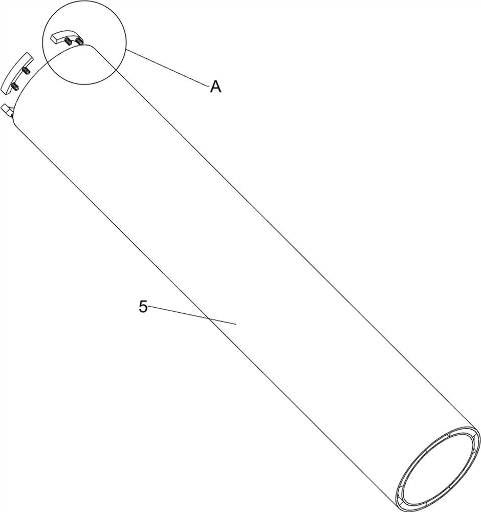
[0032] A self-rolling industrial iron plate equipment such as figure 1 , figure 2 , image 3 with Figure 4 As shown, it includes a base 1, a geared motor 2, a rolling assembly 3 and a moving assembly 4. A geared motor 2 is installed in the middle of the upper left side of the base 1, a rolling assembly 3 is provided in the middle of the upper side of the base 1, and a rolling assembly 3 is installed on the upper side of the rolling assembly 3. The moving components 4 are provided with sleeves 5 between the moving components 4 .

[0033]When the user needs to roll up the industrial iron plate, first place the iron plate on the rolling assembly 3, then fix the casing 5 in the moving assembly 4, start the deceleration motor 2, drive the rolling assembly 3 to move, and thus drive the moving assembly 4 moves, and then drives the sleeve 5 to move, so that the iron plate is rolled up by rotation, and then the sleeve 5 is removed, and the rolled up iron sheet is removed and colle...

Embodiment 2

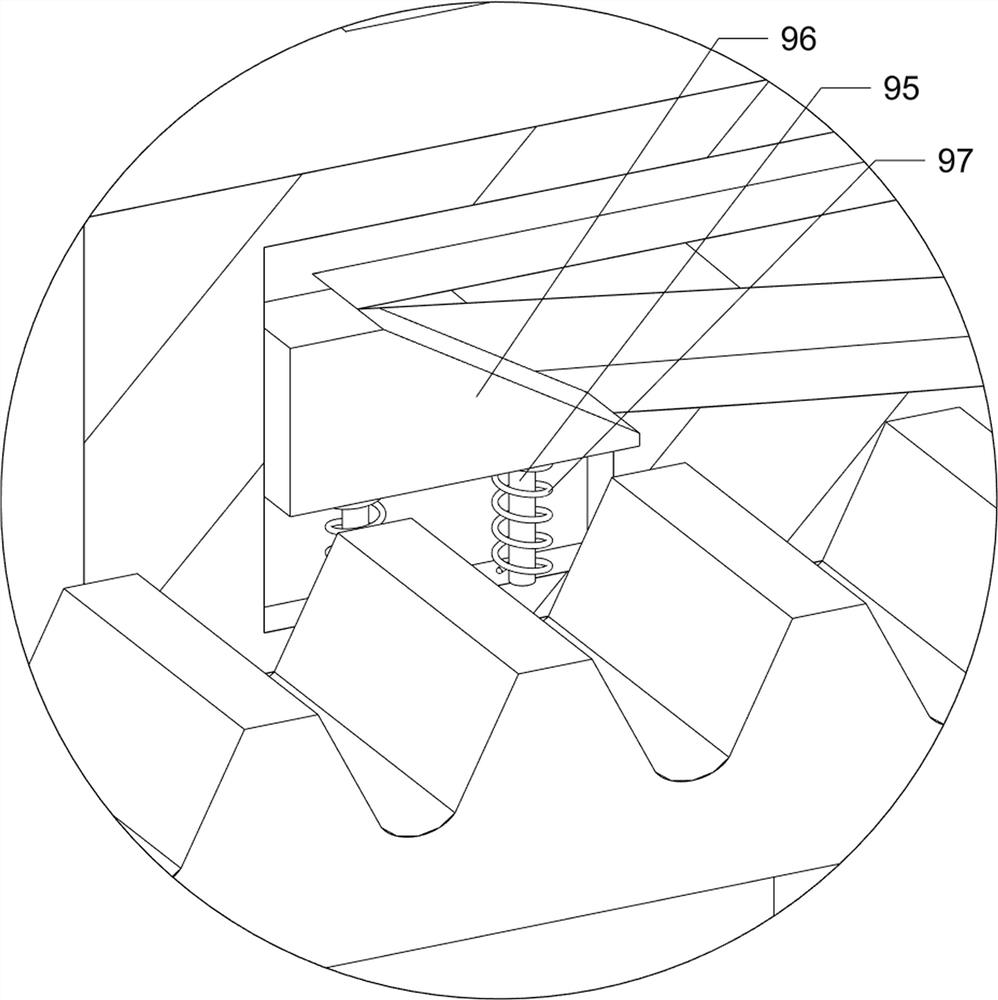
[0041] On the basis of Example 1, such as Figure 5 , Image 6 , Figure 7 , Figure 8 with Figure 9 As shown, a pedal assembly 6 is also included, and the pedal assembly 6 includes a second guide rod 61, a first connecting rod 62, a pedal 63, a third spring 64, a second connecting rod 65, a first wedge block 66 and a button 67. A second guide rod 61 is connected to the left front side of the upper part of the base 1, and a first connecting rod 62 is slidably connected to the upper side of the second guide rod 61, and a pedal 63 is connected to the upper front side of the first connecting rod 62. A third spring 64 is connected between the rod 62 and the base 1, and the third spring 64 is sleeved on the second guide rod 61. The middle parts of the two first support rods 41 on the front side are all slidably connected with the second connecting rod 65. A first wedge block 66 is connected between the upper side of the second connecting rod 65 on the side, and the first wedge...


PUM


Abstract

The invention relates to iron plate rolling equipment, in particular to automatic industrial iron plate rolling equipment. The technical problem to be solved is to provide the automatic industrial iron plate rolling equipment that an industrial iron plate is rolled efficiently and is easy to take down and collect. The automatic industrial iron plate rolling equipment comprises a base, a rolling assembly, moving assemblies and a sleeve, wherein the middle of one side of the base is provided with a reducing motor; the rolling assembly is arranged at the middle part of the upper side of the base;the moving assemblies are arranged at the upper side of the rolling assembly; and the sleeve is arranged between the moving assemblies. According to the iron plate rolling equipment, by starting thereducing motor, under the action of a series of rotating and meshing, the sleeve and a first roller are driven to rotate, so that the effect of automatically rolling up the iron plate is achieved; bystepping on a pedal, a button is pressed; the reducing motor is closed; meanwhile, a first wedge-shaped block is driven to move downwards; with the cooperation of the first wedge-shaped block and sliding blocks, the sleeve is loosened, the effects of automatically closing the reducing motor and automatically loosening the sleeve are achieved, and better discharging is facilitated.

Description

technical field [0001] The invention relates to a rolling iron plate equipment, in particular to an automatic rolling industrial iron plate equipment. Background technique [0002] Iron products, such as iron plates, have been widely used in industry due to their own characteristics. In order to make iron products better and more rationally used in various industrial fields, it is often necessary to reprocess them and transform iron products into Various forms, including the shape of rolling industrial iron plates into cylinders. [0003] At present, the existing technology of rolling industrial iron plates is that the user places a flat iron plate in the equipment, and rolls the iron plate into a cylinder through the rotation of the sleeve, and then manually disassembles the sleeve from the equipment, and finally removes the sleeve from the equipment. The coiled iron plates are removed from the casing, and the manual placement of the iron plates and the final removal of th...

Claims


Application Information

Patent Timeline
IPC IPC(8): B21D5/12B21D45/04B21D45/06B21D45/10B21D43/02
CPCB21D5/12B21D45/04B21D45/06B21D45/10B21D43/02
Inventor 不公告发明人
Owner 彭云飞
Why Eureka
Try Eureka