
Temperature control monitoring system for power distribution cabinet and power distribution cabinet

A power distribution cabinet and cabinet technology, which is applied in the substation/distribution device shell, electrical components, panel/switch station circuit devices, etc., can solve the problems of leakage, inability to adjust the speed of cooling fans, etc. The effect of reducing the probability of falling into the cabinet and improving the service life

Inactive Publication Date: 2021-03-30
王汝佳
View PDF7 Cites 0 Cited by
  • Summary
  • Abstract
  • Description
  • Claims
  • Application Information

AI Technical Summary

Problems solved by technology

[0005] Aiming at the problems in the prior art that the power distribution cabinet is prone to water ingress in rainy days, causing leakage and the speed of the cooling fan cannot be adjusted, the purpose of the present invention is to provide a temperature control monitoring system for a power distribution cabinet and a power distribution cabinet, which can dissipate heat The rainwater entering the exhaust pipe is blocked to ensure the safe operation of internal electrical equipment, and the speed of cooling fans is controlled to reduce power consumption

Method used


Image

  • Temperature control monitoring system for power distribution cabinet and power distribution cabinet
  • Temperature control monitoring system for power distribution cabinet and power distribution cabinet
  • Temperature control monitoring system for power distribution cabinet and power distribution cabinet

Examples


Embodiment

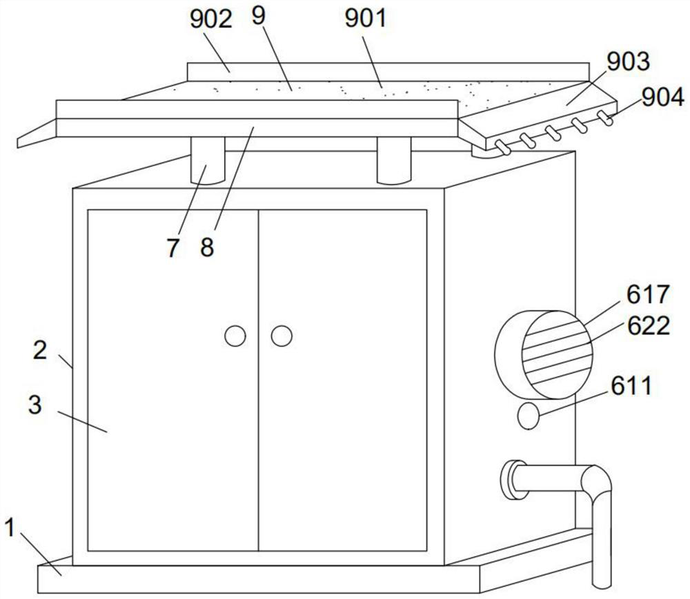
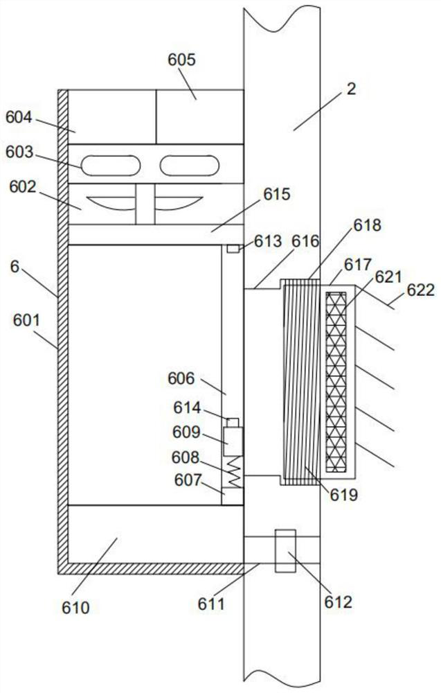
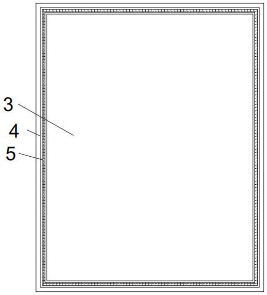
[0039] see Figure 1-7 , including the installation base 1, the top of the installation base 1 is fixedly connected with the cabinet body 2, the front of the cabinet body 2 is hinged with the cabinet door 3 through hinges, the four sides of the back side of the cabinet door 3 are provided with pad grooves 4, and the inside of the pad groove 4 is embedded There is a sealing gasket 5, a cooling device 6 is fixedly installed on the right side of the cabinet body 2, a pillar 7 is fixedly connected to the top of the cabinet body 2, a shielding cover 8 is fixedly connected to the top of the pillar 7, and a rain guide is fixedly connected to the top of the shielding cover 8 Device 9, the heat dissipation device 6 includes a heat dissipation pipe 601, the top of the heat dissipation pipe 601 is fixedly connected with a heat dissipation fan 602, and the top of the heat dissipation fan 602 is fixedly installed with a heat conduction coil 603, and the heat conduction coil 603 and the heat...


PUM


Abstract

The invention aims to provide a power distribution cabinet with rainwater draining and blocking functions. Thepower distribution cabinet can drain and block the rainwater entering from a heat dissipation exhaust pipe, thereby ensuring the safe operation of internal electrical devices. The power distribution cabinet comprises a mounting base, and a cabinet body is fixedly connected to the top of the mounting base. Thepower distribution cabinet is characterized in that a heat dissipation device is fixedly mounted at the right side of the cabinet body, the heat dissipation device comprises the heat dissipation exhaust pipe, and a sliding rail is fixedly installed at the right side of the heat dissipation exhaust pipe; a fixing block is fixedly connected to the bottom end of the interior of the sliding rail, a sealing belt is fixedly connected to the top of the fixing block, and a floating block is fixedly connected to the top of the sealing belt; a pressing block is fixedly connected to the top of the floating block, the floating block slides in the sliding rail, and a waterproof button is fixedly installed at the top end of the interior of the sliding rail; a switch valve is fixedlyinstalled at the top of the waterproof button, is electrically connected with the waterproof button through a wire, and is electrically connected with a main power supply of the cabinet body through awire.

Description

technical field [0001] The invention relates to the field of power distribution cabinets, more specifically, to a temperature control and monitoring system for a power distribution cabinet and the power distribution cabinet. Background technique [0002] Patent No. CN201720923822.6 provides a municipal high-efficiency heat dissipation power distribution cabinet, which involves the field of electric power. The municipal high-efficiency heat dissipation power distribution cabinet includes a cabinet body. A vent is opened on the left side of the cabinet body. There is a wire inlet on the side and below the air vent, the bottom of the cabinet is fixedly connected with the supporting legs, the back of the cabinet is provided with an air inlet, and a serpentine water pipe is fixed inside the air inlet. The outer surface of the snake-shaped water pipe is fixedly connected with a heat dissipation copper sheet, the inside of the cabinet is provided with a heat dissipation frame, and...

Claims


Application Information

Patent Timeline
IPC IPC(8): H02B1/28H02B1/56H02B1/30H02B1/38H02B1/24
CPCH02B1/28H02B1/565H02B1/30H02B1/38H02B1/24
Inventor 王汝佳
Owner 王汝佳
Learn More