Method and device for realizing 3D shooting and display and 3D display terminal

A display terminal, 3D technology, applied in the 3D field, can solve the problems of untimely image processing, strong dependence on the main control chip, occupying the resources of the main control chip, etc.

Pending Publication Date: 2021-03-30
BEIJING IVISUAL 3D TECH CO LTD +1
View PDF0 Cites 2 Cited by
  • Summary
  • Abstract
  • Description
  • Claims
  • Application Information

AI Technical Summary

Problems solved by technology

[0006] Embodiments of the present disclosure provide a method, device, and 3D display terminal for realizing 3D shooting and display, so as to solve the problem that a large amount of resources of the main control chip are occupied, the dependence on the main control chip is strong, and the image processing obtained by the shooting device is not timely. technical issues

Method used


Image

  • Method and device for realizing 3D shooting and display and 3D display terminal
  • Method and device for realizing 3D shooting and display and 3D display terminal
  • Method and device for realizing 3D shooting and display and 3D display terminal

Examples


Embodiment Construction

[0152] In order to understand the characteristics and technical content of the embodiments of the present disclosure in more detail, the implementation of the embodiments of the present disclosure will be described in detail below in conjunction with the accompanying drawings. The attached drawings are only for reference and description, and are not intended to limit the embodiments of the present disclosure. In the following technical description, for purposes of explanation, numerous details are set forth in order to provide a thorough understanding of the disclosed embodiments. However, one or more embodiments may be practiced without these details. In other instances, well-known structures and devices may be shown simplified in order to simplify the drawings.

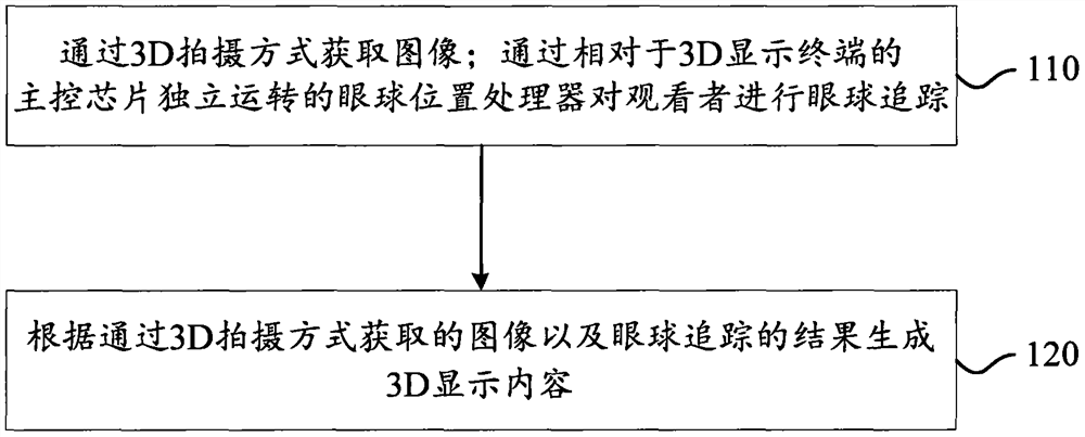
[0153] see figure 1 , an embodiment of the present disclosure provides a method for realizing 3D shooting and display, including:

[0154] Step 110: Acquiring images through 3D shooting; performing eye tracking on...


PUM


Abstract

The invention relates to the technical field of 3D, and discloses a method for realizing 3D shooting and display, which comprises the following steps: acquiring an image in a 3D shooting mode; performing eyeball tracking on a viewer through an eyeball position processor which operates independently relative to a main control chip of the 3D display terminal; and generating 3D display content according to the image acquired in the 3D shooting mode and an eyeball tracking result. According to the invention, eyeball tracking is directly carried out on a viewer through the eyeball position processor which operates independently relative to the main control chip of the 3D display terminal, and related processing is not carried out by the main control chip of the 3D display terminal, so that a large amount of resources are prevented from being occupied by the main control chip due to related processing, the dependence on the main control chip is reduced, and the timeliness of image processingis improved. The invention also discloses a device for realizing 3D shooting and display and a 3D display terminal.

Description

technical field [0001] The present application relates to the field of 3D technology, for example, to a method, a device and a 3D display terminal for realizing 3D shooting and display. Background technique [0002] At present, more and more terminals are equipped with a photographing device to obtain an image of an object to be photographed and send the image to a main control chip of the terminal for processing to obtain information in the image. [0003] In the process of implementing the embodiments of the present disclosure, it is found that at least the following problems exist in related technologies: [0004] Since the images acquired by the shooting device are sent to the main control chip of the terminal for processing, a large amount of resources of the main control chip are occupied; moreover, the main control chip needs to be started in advance and the operating system is loaded, resulting in a strong dependence on the main control chip. The images acquired by ...

Claims


Application Information

Patent Timeline
Patent Type & Authority Applications(China)
IPC IPC(8): H04N13/383H04N13/239H04N13/257H04N13/30H04N13/128H04N13/133H04N13/15
CPCH04N13/128H04N13/133H04N13/15H04N13/239H04N13/257H04N13/30H04N13/383
Inventor 不公告发明人
Owner BEIJING IVISUAL 3D TECH CO LTD
Why Eureka
Try Eureka