
Cutting device for steel strand machining and working method thereof

A steel strand and cutting technology, which is applied in the field of cutting devices for steel strand processing, can solve problems such as injury to operators, inability to accurately cut steel strands, and unfavorable steel strand cutting.

Pending Publication Date: 2021-04-02
AOSHENG MAANSHAN STEEL WIRE & WIRE ROPE
View PDF7 Cites 1 Cited by
  • Summary
  • Abstract
  • Description
  • Claims
  • Application Information

AI Technical Summary

Problems solved by technology

[0003] The patent document (202010653131.5) discloses a hydraulic cutting device, which is suitable for steel strands of different diameters. At the same time, the upper and lower positions of the cutting limit can be adjusted to ensure the accuracy of the cutting position. However, the cutting device does not take into account the steel strand When the wire is cut off, there will be springback at both ends. This situation is not conducive to the subsequent cutting of the steel strand, but may also injure the operator during the springback process. It usually occurs during the cutting of the steel strand. Due to the error caused by the stroke of the blade and the conveying of the steel strand, the steel strand cannot be cut off accurately

Method used


Image

  • Cutting device for steel strand machining and working method thereof
  • Cutting device for steel strand machining and working method thereof
  • Cutting device for steel strand machining and working method thereof

Examples


Embodiment Construction

[0033] The following will clearly and completely describe the technical solutions in the embodiments of the present invention with reference to the accompanying drawings in the embodiments of the present invention. Obviously, the described embodiments are only some, not all, embodiments of the present invention. Based on the embodiments of the present invention, all other embodiments obtained by persons of ordinary skill in the art without creative efforts fall within the protection scope of the present invention.

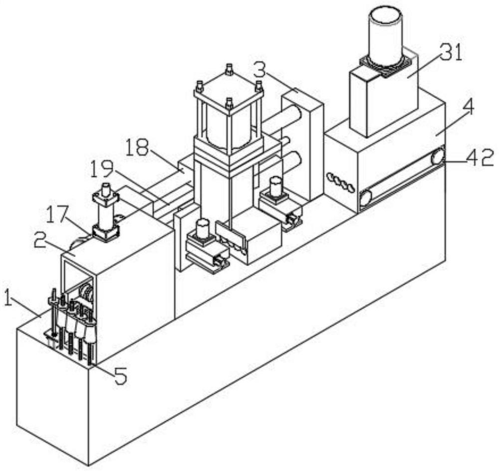
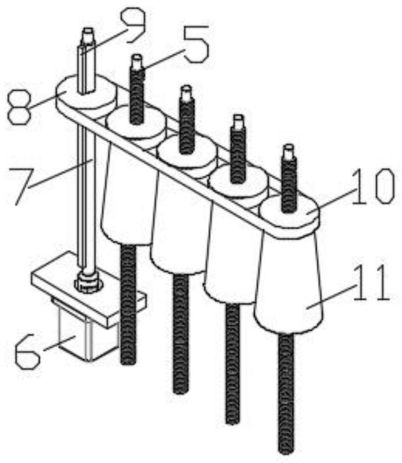
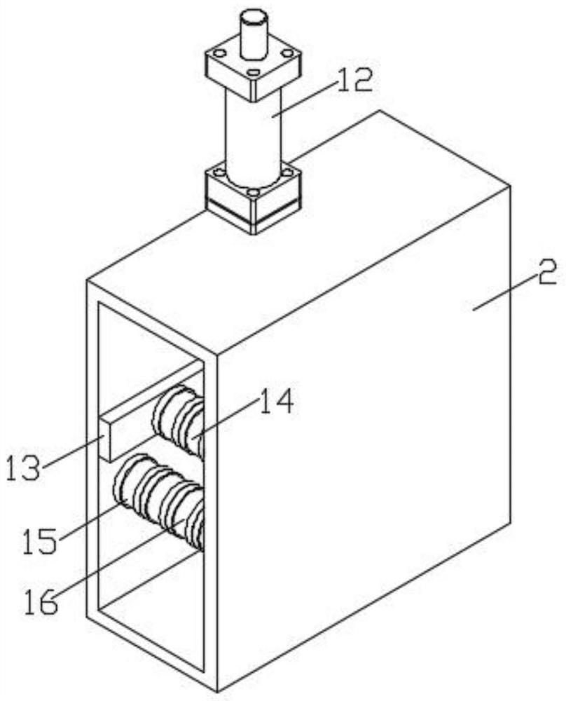
[0034] see Figure 1-7 As shown, the present invention is a cutting device for steel strand processing, including a processing table 1, on which a guide chamber 2 and a lead-out chamber 4 are installed, and two side columns are arranged between the guide chamber 2 and the lead-out chamber 4 3. A number of fixed screw rods 5 are arranged on one side of the guide chamber 2, and the screw sleeve on the fixed screw rod 5 is provided with a pulley 2 10, and a winding dr...


PUM


Abstract

The invention discloses a cutting device for steel strand machining and a working method thereof. The cutting device for steel strand machining comprises a machining table, a guide chamber and a leading-out chamber are installed on the machining table, two side columns are arranged between the guide chamber and the leading-out chamber, a plurality of fixing screws are arranged on one side of the guide chamber, the fixing screws are sleeved with pulleys II in a threaded mode, winding drums are installed on the pulleys II, the winding drums are used for winding steel strands. A plurality of steel strands can be unreeled at the same time, meanwhile, the winding drums can automatically ascend while unreeling is conducted, due to the fact that the steel strands are wound on the winding drums, it is guaranteed that the pay-off height of the winding drums can be kept consistent with that of a lower limiting rod, and the situation that the drop between the pay-off height of the winding drums and the pay-off height of the lower limiting rod is large is prevented; and through the design of two limiting belts, the situation that the steel strands rebound when cut off can be prevented, and meanwhile, the steel strands can be continuously conveyed after being cut off.

Description

technical field [0001] The invention relates to the technical field of steel strand processing, in particular to a cutting device for steel strand processing and a working method thereof. Background technique [0002] Many bridges now adopt prestressed structures, and steel strands are an indispensable part of prestressed components. The steel strands are generally very long, and what is actually needed may be only a section, and at this time the steel strands need to be cut. [0003] The patent document (202010653131.5) discloses a hydraulic cutting device, which is suitable for steel strands of different diameters. At the same time, the upper and lower positions of the cutting limit can be adjusted to ensure the accuracy of the cutting position. However, the cutting device does not take into account the steel strand When the wire is cut off, there will be springback at both ends. This situation is not conducive to the subsequent cutting of the steel strand, but may also i...

Claims


Application Information

Patent Timeline
Patent Type & Authority Applications(China)
IPC IPC(8): B21F11/00B21F9/00B21F23/00B21C47/18
CPCB21F11/00B21F9/002B21F23/00B21C47/18
Inventor 汤亮倪晓峰李红明王钧张先勇
Owner AOSHENG MAANSHAN STEEL WIRE & WIRE ROPE
Learn More