
Piston rod cutting equipment for hydraulic oil cylinder production

A technology of cutting equipment and hydraulic cylinders, applied in metal processing equipment, large fixed members, maintenance and safety accessories, etc., can solve the problems of inconvenient operation, unreliable safety, single function, etc., and achieve the effect of easy operation.

Inactive Publication Date: 2021-04-02
娄底鼎力液压科技有限公司
View PDF0 Cites 0 Cited by
  • Summary
  • Abstract
  • Description
  • Claims
  • Application Information

AI Technical Summary

Problems solved by technology

[0004] The main purpose of the present invention is to provide a piston rod cutting equipment for hydraulic cylinder production, which can effectively solve the problems of single function, unreliable safety and inconvenient operation in the background technology

Method used


Image

  • Piston rod cutting equipment for hydraulic oil cylinder production
  • Piston rod cutting equipment for hydraulic oil cylinder production
  • Piston rod cutting equipment for hydraulic oil cylinder production

Examples


Embodiment 1

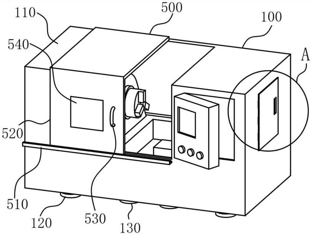
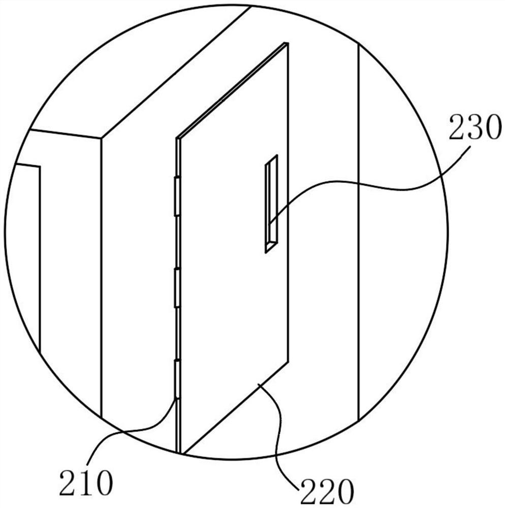
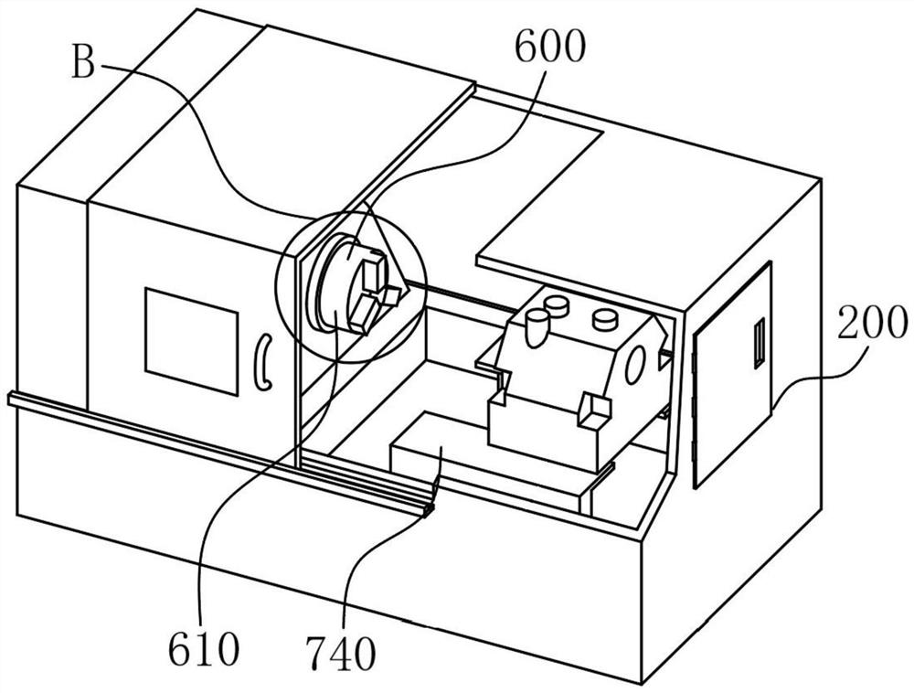
[0034] refer to figure 1—7. The present invention is a piston rod cutting equipment for hydraulic cylinder production, including a casing structure 100, a repair device 200, a control device 300, a power device 400, a sliding door mechanism 500, a cutting device 600, and a feeding device 700. The casing structure 100 includes a shell 110 and foot pads 120. The shell 110 is an internal hollow structure. One end of several foot pads 120 is welded to the outer lower surface of the shell 110. Among them, there are eight foot pads 120, and the foot pads 120 are mainly connected to the shell 110. connection, which plays the role of support. The repair device 200 includes a first hinge 210 and an alloy plate 220. One end of several first hinges 210 is connected to the outer surface of the shell 110, and several first hinges 210 are rotatably matched with the alloy plate 220. , wherein, there are three first hinges 210, the first hinge 210 is mainly connected with the alloy plate 220,...


PUM


Abstract

The invention relates to the technical field of piston rod cutting, in particular to piston rod cutting equipment for hydraulic oil cylinder production. The piston rod cutting equipment comprises a shell structure, a repairing device, a control device, a power device, a door moving mechanism, a cutting device and a feeding device, the shell structure comprises a shell, and the repairing device comprises a plurality of first hinges and an alloy plate; one end of each first hinge is connected with the surface on one side of the outer portion of the shell, the first hinges are rotationally matched with the alloy plate, the control device comprises a main panel and a plurality of second hinges, one end of each second hinge is connected with one surface of the exterior of the shell, the secondhinges are rotatably matched with the main panel, one end of a sliding rail is connected with one surface of the outer portion of the shell; and a sliding door is in sliding fit with the sliding rail.According to the piston rod cutting equipment, the power operation of a driving shaft can be controlled through the cutting device, the piston rod cutting equipment is suitable for actual situation operation in life, the machine state is controlled in time through the repairing device, and the worry-saving and safe effects are achieved.

Description

technical field [0001] The invention relates to the technical field of piston rod cutting, in particular to a piston rod cutting equipment for hydraulic oil cylinder production. Background technique [0002] The piston is a reciprocating part in the cylinder block of an automobile engine. The basic structure of the piston can be divided into top, head and skirt. The top of the piston is the main part of the combustion chamber, and its shape is related to the selected combustion chamber. Gasoline engines mostly use flat-top pistons, which have the advantage of small heat absorption area. There are often various pits on the top of diesel engine pistons, and their specific shapes, positions and sizes must be compatible with the requirements of diesel engine mixture formation and combustion. Piston components include: pistons, piston rings, support rings, piston rods, etc. According to different structural forms, pistons can be divided into cylindrical pistons, disc pistons, dif...

Claims


Application Information

Patent Timeline
Patent Type & Authority Applications(China)
IPC IPC(8): B23Q1/00B23Q1/01B23Q5/34B23Q11/08
CPCB23Q1/00B23Q1/01B23Q5/34B23Q11/08
Inventor 潘祥源
Owner 娄底鼎力液压科技有限公司
Learn More