Mechanical hydraulic control reversing valve

A hydraulically controlled reversing valve, mechanical technology, applied in the direction of mechanical equipment, multi-way valves, valve devices, etc., can solve the problems of frequent switching of the main valve, and the main valve core stops at a certain position in the middle, so as to ensure stable operation Performance and reliability, fast response, small size

Active Publication Date: 2021-04-02
SHANGHAI AEROSPACE CONTROL TECH INST
View PDF9 Cites 3 Cited by
  • Summary
  • Abstract
  • Description
  • Claims
  • Application Information

AI Technical Summary

Problems solved by technology

However, in the above design, when the oil pressure of the main oil source fluctuates around the set switching pressure, the main valve will still switch frequently and vibrate
In addition, the displacement of the main spool will also change with the pressure, and there is a risk that the main spool will stop somewhere in the middle

Method used


Image

  • Mechanical hydraulic control reversing valve
  • Mechanical hydraulic control reversing valve
  • Mechanical hydraulic control reversing valve

Examples


Embodiment 1

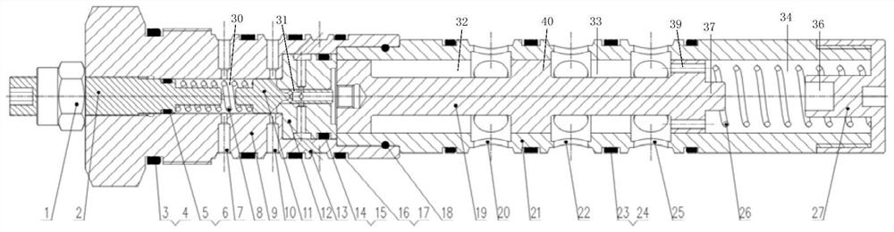
[0061] The invention provides a mechanical hydraulic control reversing valve, such as figure 1 As shown, it includes a first adjustment mechanism, a second adjustment mechanism, a pilot valve sleeve 9, an oil chamber switching mechanism, a main valve core 19 and a main valve sleeve 21. One end of the pilot valve sleeve 9 is equipped with a first adjustment mechanism, so One end of the main valve sleeve 21 is installed with a second adjustment mechanism, the other end of the pilot valve sleeve 9 is connected to the other end of the main valve sleeve 21 and an installation chamber is formed inside, the oil chamber switching mechanism, the main valve core 19 are sequentially arranged in the installation chamber along the direction from the first adjustment mechanism to the second adjustment mechanism, a first accommodation space 30 is formed between the oil chamber switching mechanism and the first adjustment mechanism, and the oil chamber switching mechanism The first pilot cavi...

Embodiment 2

[0077] This embodiment is a preferred example of Embodiment 1.

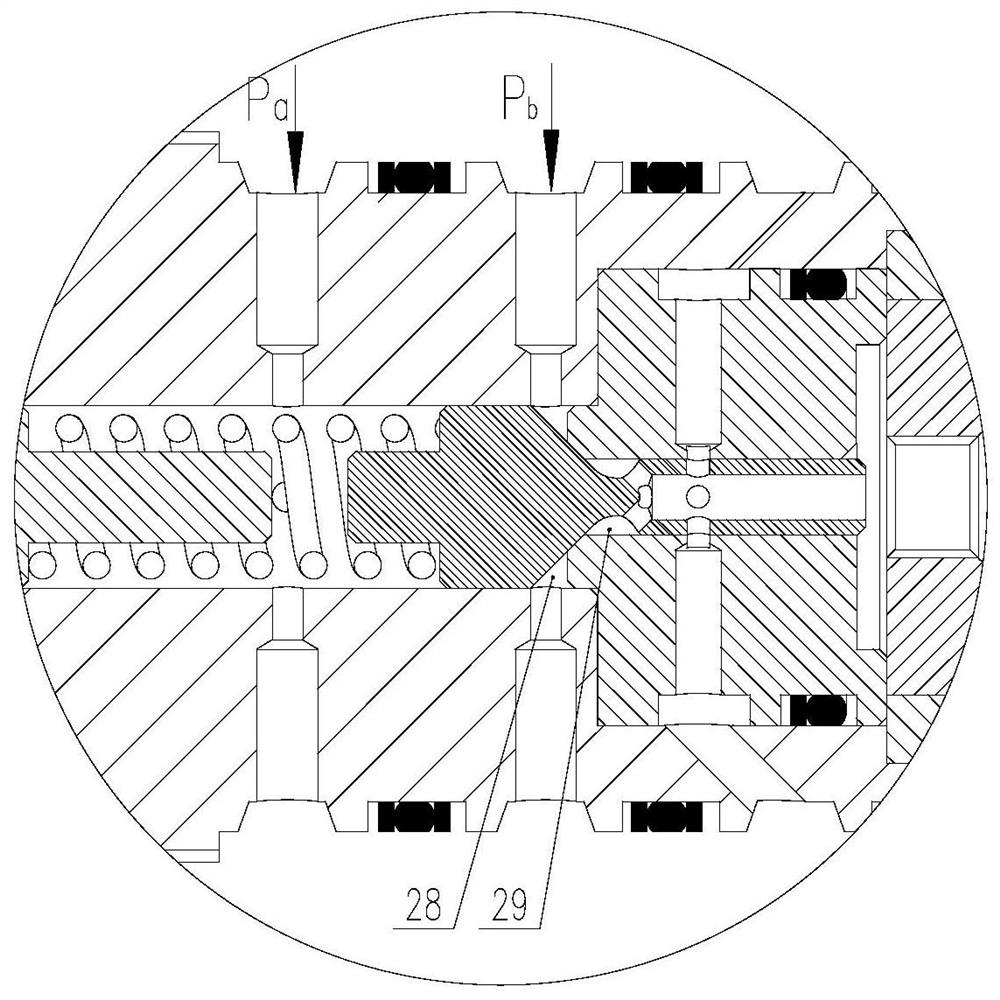
[0078] Such as Figure 4 , Figure 5As shown, the valve block in this embodiment has a main oil source port, an auxiliary oil source port, a load port and an oil return port. When the oil pressure of the two oil sources is normal, the pilot spool 11 is in the closed state, and the main spool 19 is always at the leftmost position under the action of the main valve spring 26 and the oil pressure of the main spool spring cavity. At this time, the load oil port is connected with the main oil source oil port, and the main oil source supplies oil in the working state. When the oil supply pressure of the main oil source is lower than the second preset oil pressure, the pilot spool 11 opens, and the oil pressure of the main valve spool 19 in the left chamber of the main valve, the spring force of the main valve and the oil pressure in the spring chamber of the main spool Move down to the rightmost position under actio...


PUM


Abstract

The invention provides a mechanical hydraulic control reversing valve, which comprises a first adjusting mechanism, a second adjusting mechanism, a pilot valve sleeve, an oil chamber switching mechanism, a main valve core and a main valve sleeve; the first adjusting mechanism and the second adjusting mechanism are respectively arranged at one end of the pilot valve sleeve and one end of the main valve sleeve; the other end of the pilot valve sleeve is connected with the other end of the main valve sleeve, and an installation cavity is formed in the pilot valve sleeve; the oil chamber switchingmechanism and the main valve element are sequentially arranged in the installation cavity; a first containing space, a first pilot cavity, a second containing space and a third containing space are formed in the installation cavity; the first containing space and the third containing space are connected with a main oil source; and the first pilot cavity and the second containing space are respectively connected with an auxiliary oil source. When the pilot valve is opened and closed, the acting area of one side of the pilot valve is changed, so that the pressure required for the opening and closing of the pilot valve is different, so that the working stability and reliability of the reversing valve are ensured, and the risk that the main valve core stops at a certain position in the middleis avoided.

Description

technical field [0001] The invention relates to the fields of hydraulic valves and fluid transmission control, in particular to a mechanical hydraulic control reversing valve. Background technique [0002] The reversing valve is a directional control valve with more than two flow forms and more than two oil ports. It is a valve that realizes the communication, cut-off and reversing of hydraulic oil flow, as well as pressure unloading and sequential action control. In the hydraulic servo system, when the oil source fails and the oil supply pressure drops greatly, in order to make the load continue to work, an auxiliary oil source is usually set up. Therefore, a reversing device is needed to realize the switching device of the main oil source and the auxiliary oil source. Because the hydraulic control directional valve has higher reliability than the electromagnetic directional valve, it is widely used. Screw-in cartridge hydraulic valves are widely used in existing hydraul...

Claims


Application Information

Patent Timeline
Patent Type & Authority Applications(China)
IPC IPC(8): F15B13/02F16K11/07F16K31/12
CPCF15B13/02F16K11/07F16K31/12
Inventor 李文顶誾耀保李双路纪宝亮刘敏鑫董文勇王东刘洪宇傅俊勇
Owner SHANGHAI AEROSPACE CONTROL TECH INST
Why Eureka
Try Eureka