Backlight module circuit and liquid crystal display device

A backlight module and circuit technology, applied in static indicators, instruments, etc., can solve problems such as difficulties, and achieve the effect of high-bit number and delicate screen display

Active Publication Date: 2021-04-02
TCL CHINA STAR OPTOELECTRONICS TECH CO LTD
View PDF6 Cites 4 Cited by
  • Summary
  • Abstract
  • Description
  • Claims
  • Application Information

AI Technical Summary

Problems solved by technology

[0003] At present, the backlight with a high bit (bit) number in the LCD display can achieve a more delicate picture display, so increasing the bit (bit) number must be the development trend of LCD display technology in the future; however, it is limited by the LCD charging time and charging delay. Influenced by other factors, it is difficult to achieve a high bit (bit) number in the LCD display

Method used


Image

  • Backlight module circuit and liquid crystal display device
  • Backlight module circuit and liquid crystal display device
  • Backlight module circuit and liquid crystal display device

Examples


Embodiment 1

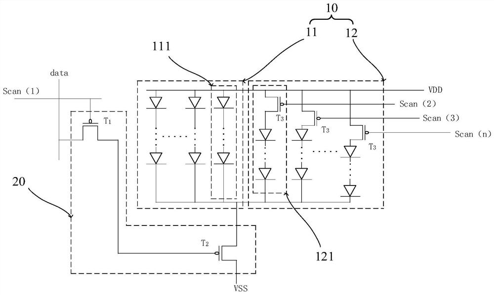
[0041] see image 3 , the first circuit diagram of the backlight module circuit provided by the embodiment of the present application.

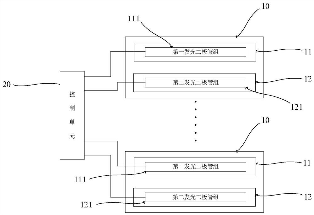
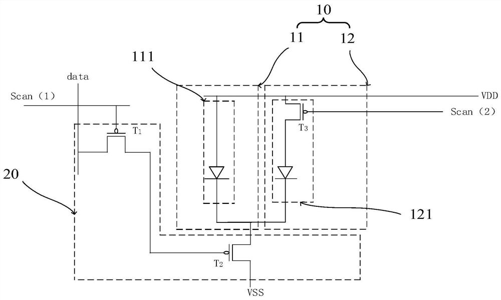
[0042]In this embodiment, the backlight module circuit includes a plurality of partitioned backlight units 10 and a control unit 20; any of the partitioned backlight units 10 includes an LED main area 11 and an LED sub area 12; the LED main area The light-emitting diodes in zone 11 and the light-emitting diodes in the light-emitting diode sub-zone 12 are connected in parallel to the control unit 20 .

[0043] The control unit 20 is used for turning on the LEDs in the main LED area 11 and the LEDs in the sub LED area 12 .

[0044] In this embodiment, the LED main area 11 includes M parallel first LED groups 111; the LED sub area 12 includes N parallel second LED groups 121; any of the first The light-emitting diode group 111 and any of the second light-emitting diode groups 121 include a plurality of series-connected light-emitting diodes; t...

Embodiment 2

[0062] This embodiment also provides a liquid crystal display device, the liquid crystal display device includes a liquid crystal screen and a backlight module circuit, and the backlight module circuit provides backlight for the liquid crystal screen.

[0063] The backlight module circuit has been described in detail in the first embodiment above, so it will not be repeated here.

[0064] The application provides a backlight module circuit and a liquid crystal display device. The backlight module circuit includes a plurality of partitioned backlight units and a control unit; the light emitting diodes in the light emitting diode main area and the light emitting diodes in the light emitting diode sub area are connected in parallel to the control unit; the control unit is used to light the light emitting diodes in the light emitting diode main area and the light emitting diode Light-emitting diodes in the light-emitting diode sub-area; wherein, the light-emitting diode sub-area i...


PUM


Abstract

The invention provides a backlight module circuit and a liquid crystal display device. The backlight module circuit comprises a plurality of partition backlight units and a control unit. Any partitionbacklight unit comprises a light-emitting diode in the light-emitting diode main area and a light-emitting diode in the light-emitting diode auxiliary area; the light emitting diode in the light emitting diode main area and the light emitting diode in the light emitting diode auxiliary area are connected to the control unit in parallel. The partition backlight unit is divided into a light-emitting diode main area and a light-emitting diode auxiliary area; a control switch is additionally arranged in each second light emitting diode group in the light emitting diode auxiliary area to adjust the brightness of the light emitting diode auxiliary area, so the gray scale number of the light emitting diodes in the light emitting diode main area and the light emitting diodes in the light emittingdiode auxiliary area after parallel connection is increased, and the backlight unit reaches a higher bit number; and thus, finer picture display of the liquid crystal screen is realized.

Description

technical field [0001] The present application relates to the field of display technology, in particular to a backlight module circuit and a liquid crystal display device. Background technique [0002] With the rapid development of LCD display technology and the large-scale application of LED backlight modules, the response speed and picture quality of LCD TVs have made great progress. Among them, the mini LED backlight adopts an active structure and a matrix distribution, and uses TFT devices to control the light-emitting diodes to emit light, which can achieve multiple partitions, which is conducive to the realization of higher-quality display of the whole TV. [0003] At present, the backlight with a high bit (bit) number in the LCD display can achieve a more delicate picture display, so increasing the bit (bit) number must be the development trend of LCD display technology in the future; however, it is limited by the LCD charging time and charging delay. Due to the infl...

Claims


Application Information

Patent Timeline
Patent Type & Authority Applications(China)
IPC IPC(8): G09G3/34
CPCG09G3/342
Inventor 李利霞
Owner TCL CHINA STAR OPTOELECTRONICS TECH CO LTD
Why Eureka
Try Eureka