Fishing rod and grab handle component

A technology for fishing rods and handles, which is applied in fishing rods, applications, fishing, etc., and can solve problems such as complex structures

Pending Publication Date: 2021-04-06
SHIMANO INC
View PDF3 Cites 0 Cited by
  • Summary
  • Abstract
  • Description
  • Claims
  • Application Information

AI Technical Summary

Problems solved by technology

However, it is necessary to have a middle line inside the rod main body, and the structure becomes complicated

Method used


Image

  • Fishing rod and grab handle component
  • Fishing rod and grab handle component
  • Fishing rod and grab handle component

Examples


Embodiment Construction

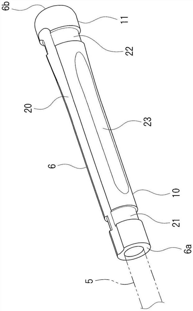
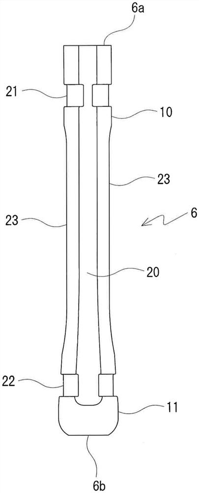
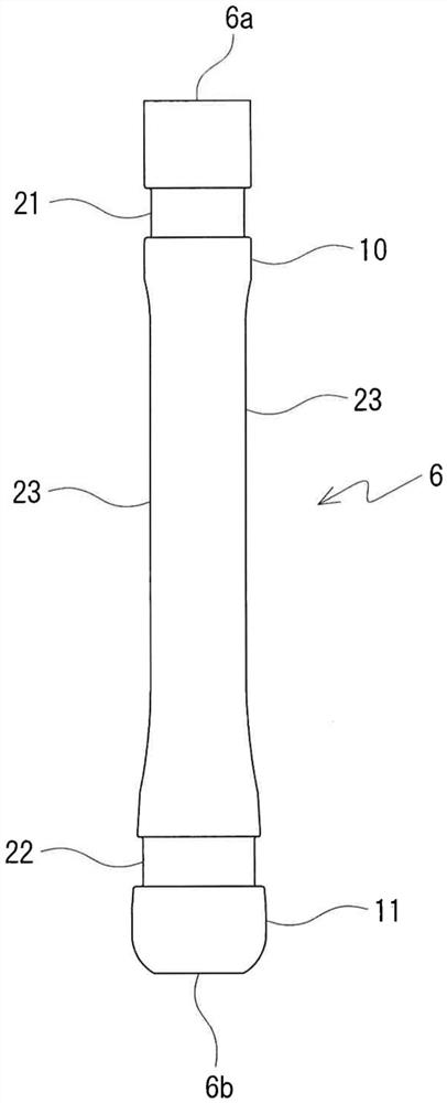
[0024] Below, refer to Figure 1 to Figure 7 , The grip member for fishing rods which concerns on one Embodiment of this invention, and the fishing rod provided with the said grip member are demonstrated. In addition, in the following description, the rod tip side is referred to as the front side, the rod tail side is referred to as the rear side, and the direction of the center line of the fishing rod is referred to as the front-rear direction. like Figure 6 and Figure 7 As shown, the fishing rod 1 of this embodiment is provided with the reel holder 2 for attaching various reels. The reel seat 2 is disposed on the fishing rod 1 at a position separated by a predetermined length from the rear end (the end on the tail side) toward the front. An electric cord reel 3 can be attached to the cord reel stand 2 . The electric reel 3 is located on the upper side of the fishing rod 1 when in use, that is, when fishing. The electric cord reel 3 is connected to an external power su...


PUM


Abstract

The invention provides a fishing rod and a grab handle component which are not easy to hinder a power line of an electric winder and are simple in structure. The fishing rod of the present invention is provided with a reel seat to which an electric reel is mounted, a wire support surface (20) that is recessed further toward the center side than other portions in the entire outer peripheral surface and circumferential grooves (21, 22) that cross the wire support surface (20) are formed on the outer peripheral surface closer to the rod tail side than the reel seat, the wire support surface (20) extending in the direction of the center line of the fishing rod, and a plurality of circumferential grooves (21, 22) are formed at intervals in the direction of the center line of the fishing rod.

Description

technical field [0001] The present invention relates to a fishing rod equipped with an electric reel and a handle part for the fishing rod. Background technique [0002] A power line is connected between the electric line reel mounted on the line reel seat of the fishing rod and the external power supply. The electric cord reel is powered from an external power source via a power cord. This cord can sometimes get in the way of fishing. In order to solve this problem, Patent Document 1 below proposes a structure in which an intermediate line is provided inside the pole main body. In this fishing rod, the reel connecting wire is connected to the electric reel, and the end of the reel connecting wire is connected to the middle wire through the side hole of the rod body. In addition, the power line is connected to the middle line at the tail portion of the main body of the pole. However, it is necessary to provide an intermediate line inside the pole main body, and the struc...

Claims


Application Information

Patent Timeline
Patent Type & Authority Applications(China)
IPC IPC(8): A01K87/08A01K87/06
CPCA01K87/08A01K87/06
Inventor 谷口一真山中贵弘
Owner SHIMANO INC
Why Eureka
Try Eureka