Clamp for machining mold insert

A technology for processing molds and inserts, applied in workpiece clamping devices, metal processing mechanical parts, manufacturing tools, etc., can solve problems such as inconvenience, and achieve the effect of improving efficiency and high degree of automation

Inactive Publication Date: 2021-05-28
深圳市康铨机电有限公司
View PDF6 Cites 1 Cited by
  • Summary
  • Abstract
  • Description
  • Claims
  • Application Information

AI Technical Summary

Problems solved by technology

[0003] In view of the above-mentioned related technologies, the inventor believes that some inserts need to be processed on both sides. When the insert is to be turned over, it is necessary to loosen the clamp, manually turn over the insert, and then operate the clamp to clamp the insert, which is inconvenient.

Method used


Image

  • Clamp for machining mold insert
  • Clamp for machining mold insert
  • Clamp for machining mold insert

Examples


Embodiment Construction

[0034] The following is attached Figure 1-5 The application is described in further detail.

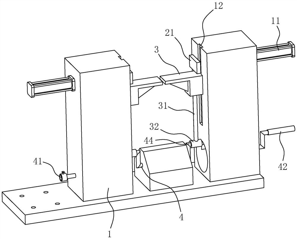
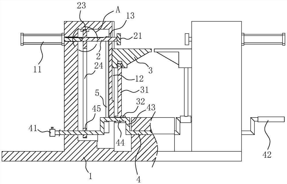
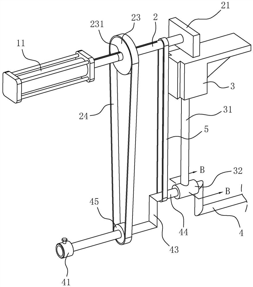
[0035] The embodiment of the present application discloses a fixture for processing mold inserts. refer to figure 1 and figure 2 , the fixture used for processing mold inserts includes a base 1, on which there are two cylinders 11, and two sliding rods 2 driven and slid by the two cylinders 11 respectively, the axial direction and sliding direction of the sliding rods 2 are all along the horizontal direction, the axes of the two sliders 2 coincide. The end of the slide bar 2 facing away from the cylinder 11 is fixed with a clamping block 21, and when the cylinder 11 drives the slide bar 2 to slide, the clamping block 21 plays the role of clamping and loosening the insert. The base 1 is slidably provided with two support blocks 3 along the vertical direction, and the two support blocks 3 are located directly below the two clamping blocks 21 respectively, and the support blocks 3 ...


PUM


Abstract

The invention relates to the field of molds, in particular to a clamp for machining a mold insert. The clamp comprises a base, two air cylinders and sliding rods driven by the air cylinders to slide correspondingly are arranged on the base, clamping blocks are arranged at the end parts, deviating from the air cylinders, of the sliding rods and are used for clamping the insert, the base is provided with a driving mechanism and a supporting block driven by the driving mechanism to ascend and descend, the supporting block is used for making contact with the bottom surface of the insert, the driving mechanism comprises a main shaft arranged on the base in a rotating mode, a crank is fixed to the main shaft, an eccentric shaft is fixed to the end part, deviating from the main shaft, of the crank and is sleeved with a rotating sleeve, a connecting rod is fixed to the rotating sleeve, and the end part, deviating from the rotating sleeve, of the connecting rod is hinged to the supporting block. According to the clamp, the insert can be turned over without loosening the clamp, the clamp does not need to be operated to clamp the insert after the insert is turned over, convenience is achieved, and therefore the efficiency is improved; the bottom surface of the insert can be stably supported, and the clamping blocks are not liable to hindering machining of the top surface of the insert; and when the main shaft rotates, rotation of the clamping blocks and the insert can be automatically completed, and the automation degree is high.

Description

technical field [0001] The present application relates to the field of molds, in particular to a fixture for processing mold inserts. Background technique [0002] In the mold, the insert refers to the mold accessories used to be embedded in the mold, which plays the role of fixing the template and filling the space between the templates. When the mold often needs to be modified, inserts can be added to the modified mold in advance. When the mold is changed in the future, only the inserts need to be replaced, and even several spare parts of the inserts can be made for replacement when the mold is opened, which is convenient for mold modification. For the processing of mold inserts, it is necessary to clamp them with fixtures for processing. [0003] In view of the above-mentioned related technologies, the inventor believes that some inserts need to be processed on both sides. When the insert is to be turned over, it is necessary to loosen the clamp, manually turn over the i...

Claims


Application Information

Patent Timeline
Patent Type & Authority Applications(China)
IPC IPC(8): B25B11/00B25H1/10B23Q3/00B23Q7/00
CPCB25B11/00B25H1/10B23Q3/00B23Q7/00B23Q2703/10
Inventor 徐宁秦建忠过冬玉柳锐唐敏
Owner 深圳市康铨机电有限公司
Why Eureka
Try Eureka