Plate punching and grinding device for intelligent manufacturing

An intelligent manufacturing and punching technology, which is applied in the direction of manufacturing tools, wood processing equipment, fixed drilling machines, etc., can solve the problems of easy sore hands and low work efficiency

Inactive Publication Date: 2021-04-06
南京伟悦烨电子商务有限公司
View PDF0 Cites 6 Cited by
  • Summary
  • Abstract
  • Description
  • Claims
  • Application Information

AI Technical Summary

Problems solved by technology

[0004] In order to overcome the shortcoming that one hand needs to hold the plate, and the other hand holds the punching tool to punch the plate, the hand is prone to soreness, and the person can only punch one hole at a time, resulting i

Method used


Image

  • Plate punching and grinding device for intelligent manufacturing
  • Plate punching and grinding device for intelligent manufacturing
  • Plate punching and grinding device for intelligent manufacturing

Examples


Embodiment 1

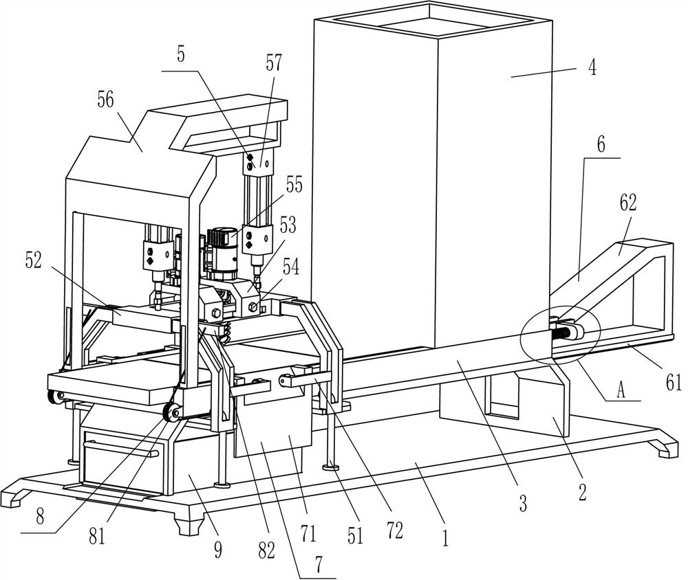
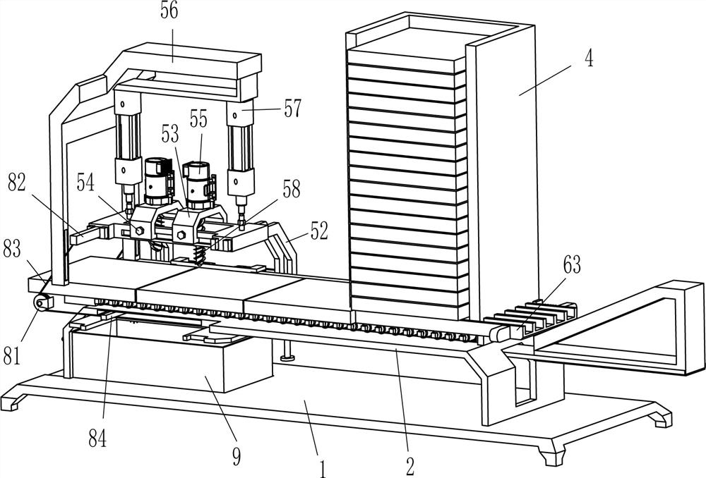
[0026] A plate punching and grinding device for intelligent manufacturing, as shown in the figure, figure 2 and Figure 4 As shown, it includes a base 1, a perforated n-type plate 2, a perforated frame body 3, a feeding frame 4, a punching and polishing mechanism 5, and a pushing mechanism 6. The top of the base 1 is fixed with a perforated n-type plate 2 , the outer top of the n-type plate with holes 2 is fixedly connected with a frame with holes 3, and the right side of the top of the frame with holes 3 is fixedly connected with a discharge frame 4, and a pusher is arranged between the discharge frame 4 and the frame with holes 3 Mechanism 6, the left part of frame body 3 with holes is provided with punching and polishing mechanism 5, and punching and polishing mechanism 5 is fixedly connected with pusher mechanism 6.

[0027] The punching and polishing mechanism 5 includes an L-shaped rod 51, a mounting frame 52, an n-shaped block 53, a fastening bolt 54, a drive motor 55...

Embodiment 2

[0033] On the basis of Example 1, such as figure 1 , figure 2 , image 3 and Figure 5 As shown, a clamping mechanism 7 is also included. The clamping mechanism 7 includes an inclined plate 71, an L-shaped contact rod 72, a splint 73 and a second spring 74. Be connected with slant plate 71, front side slant plate 71 rear side and rear side slant plate 71 front sides are all fixedly connected with splint 73, front side slant plate 71 inner front side upper left and right sides and frame body 3 outside front left side The second spring 74 is connected between the sides, and the second spring 74 is also connected between the left and right sides of the upper part of the rear side of the rear inclined panel 71 and the left side of the outer rear side of the frame body 3 with holes. L-shaped contact rods 72 are fixedly connected to the lower parts of the left and right sides, and the inner ends of the L-shaped contact rods 72 contact and cooperate with the inclined surfaces of ...

Embodiment 3

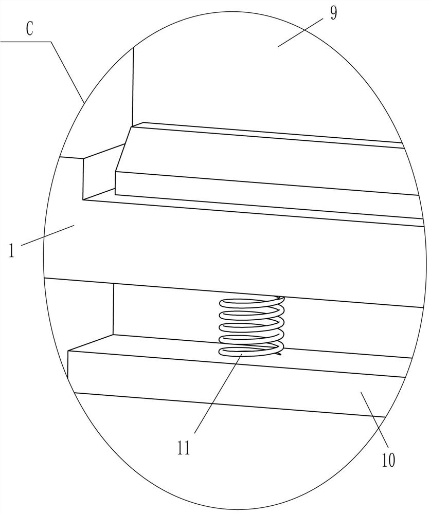
[0038] On the basis of embodiment 1 and embodiment 2, such as figure 1 , figure 2 , image 3 and Image 6 As shown, it also includes a charging frame 9, a limiting plate 10 and a fourth spring 11. The charging frame 9 is placed slidingly in the middle on the left side of the top of the base 1, and the sliding limiting plate is inserted in the middle of the left part of the base 1. 10. The limiting plate 10 is located on the left side of the charging frame 9 in contact with it, and two fourth springs 11 are connected between the left and right sides of the inner bottom of the limiting plate 10 and the bottom of the base 1 .

[0039] Also comprise movable block 12, guide roller 13 and the 5th spring 14, the frame body with hole 3 inner bottom front and back both sides inside both sides all sliding type is provided with movable block 12, movable block 12 bottom and frame body 3 with hole A fifth spring 14 is connected between them, and a guide roller 13 is rotatably connected...


PUM


Abstract

The invention relates to a grinding device, in particular to a plate punching and grinding device for intelligent manufacturing. The technical problem is how to design the plate punching and grinding device for intelligent manufacturing which is capable of replacing manual work for punching plates, avoiding hand aches and being used for punching two holes at a time and high in working efficiency. The plate punching and grinding device for intelligent manufacturing comprises a base, wherein an n-shaped plate with holes is fixedly connected to one side of the base. A proper quantity of plates are put into a material containing frame, a punching and grinding mechanism is started, the punching and grinding mechanism operates to drive a material pushing mechanism to operate, the material pushing mechanism operates to be separated from the plates, the lowest plate falls into a frame body with the holes, the punching and grinding mechanism resets to drive the material pushing mechanism to reset, the plates move leftwards, and then the punching and grinding mechanism operates again to punch the plates, so that manual punching is not needed, and the hand aches are avoided.

Description

technical field [0001] The invention relates to a grinding device, in particular to a plate punching and grinding device for intelligent manufacturing. Background technique [0002] In intelligent manufacturing, some products need to use plates, but the plates need to be punched before use, which is convenient for the subsequent use of the plates and does not affect product manufacturing. At present, most of the plates are manually punched, and one hand is required. Holding the plate, the other hand holds a punching tool to punch the plate. After a long time, the hand is prone to soreness, and a person can only punch one hole at a time, resulting in low work efficiency. [0003] Therefore, it is necessary to design and develop an intelligent manufacturing plate punching and grinding device that can replace manual punching, avoid hand pain, and can punch two holes at a time with high work efficiency. Contents of the invention [0004] In order to overcome the shortcoming t...

Claims


Application Information

Patent Timeline
IPC IPC(8): B27C3/02B27G3/00
CPCB27C3/02B27G3/00
Inventor 丁伟烨
Owner 南京伟悦烨电子商务有限公司
Why Eureka
Try Eureka