
Automatic winding copper wire fixing device for mass production hollow part electroplating

A technology for fixing devices and hollow parts, which is applied in the field of electroplating and automatically winding copper wire fixing devices for mass production of hollow parts, and can solve problems such as low efficiency and affecting efficiency

Inactive Publication Date: 2021-04-06
郑州强贵电子科技有限公司
View PDF0 Cites 0 Cited by
  • Summary
  • Abstract
  • Description
  • Claims
  • Application Information

AI Technical Summary

Problems solved by technology

[0002] With the development of science and technology, electroplating products can be seen everywhere in our life, and with the promotion of electroplating products, people's demand for electroplating products is also increasing, but there are many problems in the process of electroplating that affect efficiency During the process of electroplating, it is necessary to fix the workpiece to be electroplated with copper wire, but now most of the fixations before electroplating are mostly manually fixed, resulting in low efficiency during processing

Method used


Image

  • Automatic winding copper wire fixing device for mass production hollow part electroplating
  • Automatic winding copper wire fixing device for mass production hollow part electroplating
  • Automatic winding copper wire fixing device for mass production hollow part electroplating

Examples


Embodiment Construction

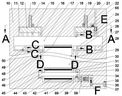
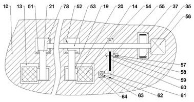
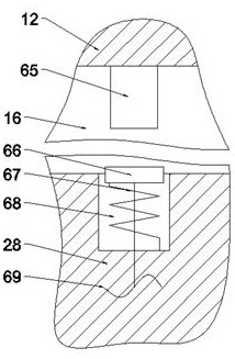
[0021] Combine below Figure 1-8 The present invention is described in detail, wherein, for the convenience of description, the orientations mentioned below are defined as follows: figure 1 The up, down, left, right, front and back directions of the projection relationship itself are the same.

[0022] A mass-produced hollow part electroplating automatic winding copper wire fixing device described in conjunction with accompanying drawings 1-8 includes a main box body 10, and an upper fixing cavity 16 that runs through the front and back is provided in the main box body 10, and the upper fixing cavity The upper side of the cavity 16 is connected with two reciprocating fixed block cavities 11 arranged symmetrically around the upper fixed cavity 16, and the upper side of the reciprocated fixed block cavity 11 is connected with a reciprocating rack cavity 13. The inner side of the bar cavity 13 is communicated with the reciprocating gear cavity 19 located on the upper side of the...


PUM


Abstract

The invention relates to the related field of industrial electroplating, and discloses an automatic winding copper wire fixing device for mass production hollow part electroplating. The automatic winding copper wire fixing device comprises a main box body, an upper fixing cavity penetrating front and back is formed in the main box body, the upper side of the upper fixing cavity communicates with two or more reciprocating fixing block cavities which are symmetrically arranged left and right with the fixing cavity as the center. Reciprocating rack cavities are formed in the upper sides of the reciprocating fixing block cavities in a communicating mode, reciprocating gear cavities located in the upper sides of the reciprocating fixing block cavities are formed in the inner sides of the reciprocating rack cavities in a communicating mode, and the purpose of winding the two ends of a fixing rod is achieved by controlling a copper wire to pass through an upper spiral guide groove and a fixed extending cavity. Under the driving of an extending guide cavity and a contact guide belt, the copper wire penetrates through a workpiece belt wheel cavity and a workpiece through hole in the workpiece belt wheel cavity to connect the workpiece with the fixed rod, and finally, a grooved wheel shaft is driven to rotate through the meshing of a grooved wheel shifting block and a four-grooved wheel, so that the wound workpiece and the fixed rod are replaced, and the purpose of reciprocating winding is achieved.

Description

technical field [0001] The invention relates to the related field of industrial electroplating, in particular to an automatic winding copper wire fixing device for mass-produced hollow parts electroplating. Background technique [0002] With the development of science and technology, electroplating products can be seen everywhere in our life, and with the promotion of electroplating products, people's demand for electroplating products is also increasing, but there are many problems in the process of electroplating that affect efficiency In the process of electroplating, it is necessary to fix the workpiece to be electroplated with copper wire, but now most of the fixations before electroplating are mostly manually fixed, resulting in low efficiency during processing. Contents of the invention [0003] The purpose of the present invention is to provide a mass-produced hollow part electroplating automatic winding copper wire fixing device, which can overcome the above-menti...

Claims


Application Information

Patent Timeline
IPC IPC(8): C25D17/06C25D7/04
CPCC25D7/04C25D17/06
Inventor 金定蔷
Owner 郑州强贵电子科技有限公司
Learn More