
High-speed rail platform antiskid ground paving structure and paving method thereof

A platform and pavement technology, which is applied to the anti-slip floor pavement structure of high-speed railway platforms and its pavement field, can solve the problems of damage to anti-slip floor tiles, inconvenient removal of anti-slip floor tiles, and loss of workload.

Inactive Publication Date: 2021-04-06
济南华锐铁路机械制造有限公司
View PDF50 Cites 0 Cited by
  • Summary
  • Abstract
  • Description
  • Claims
  • Application Information

AI Technical Summary

Problems solved by technology

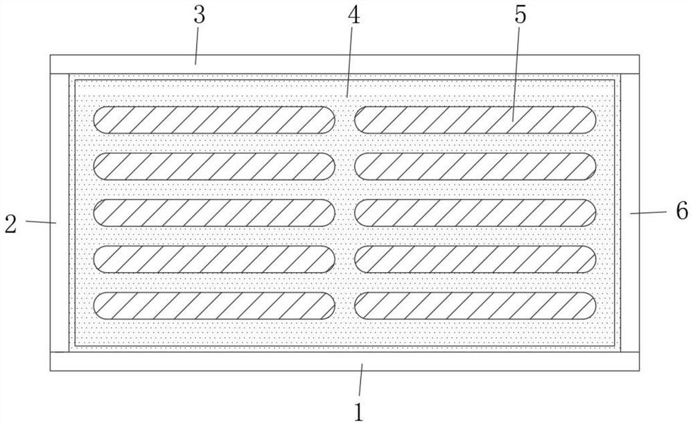
[0006] The object of the present invention is to provide a kind of high-speed rail platform non-slip ground pavement structure and its pavement method, equipped with a frame composed of a first partition, a second partition, a third partition and a fourth partition, and the frame is fixed on the ground by cement. On the platform, the anti-skid floor tiles are embedded in the frame, which is convenient to replace the damaged anti-skid floor tiles while fixing the anti-skid floor tiles. It solves the problem that it is inconvenient to remove the damaged anti-skid floor tiles due to the relationship between the cement and requires staff to smash the anti-skid floor tiles And solidified cement, if you are not careful, you may damage the good non-slip floor tiles next to it, causing greater losses and more workload problems

Method used


Image

  • High-speed rail platform antiskid ground paving structure and paving method thereof
  • High-speed rail platform antiskid ground paving structure and paving method thereof
  • High-speed rail platform antiskid ground paving structure and paving method thereof

Examples


Embodiment 1

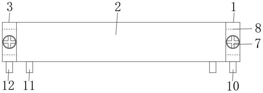
[0032] see Figure 1 to Figure 7 , an embodiment provided by the present invention: a high-speed rail platform anti-slip ground pavement structure, including a first partition 1, a second partition 2, a third partition 3, non-slip floor tiles 4, a fourth partition 6 and screws 7. Both sides of the first partition 1 and the third partition 3 are respectively provided with insertion holes 17 , and the insertion holes 17 run through the front and rear surfaces of the first partition 1 and the third partition 3 . The middle of the two ends of the first partition 1 and the third partition 3 are respectively provided with a first screw hole 18, and the middle of the two ends of the second partition 2 and the fourth partition 6 are respectively fixed with a plug-in block 8, and on the plug-in block 8 A second screw hole 19 is opened. The size of the first dividing plate 1, the second dividing plate 2, the third dividing plate 3 and the fourth dividing plate 6 can be selected accordi...

Embodiment 2

[0035] see Figure 4, an embodiment provided by the present invention: a high-speed rail platform anti-slip ground pavement structure, the first flat plate 13 is fixed on the bottom of the back of the first partition 1, and the bottom of the side of the second partition 2 opposite to the third partition 3 A second flat plate 14 is fixed, a third flat plate 15 is fixed at the bottom of the side of the third partition 3 opposite to the second partition 2 , and a fourth flat 16 is fixed at the bottom of the front of the fourth partition 6 . The bottom end surfaces of the first dividing plate 1, the second dividing plate 2, the third dividing plate 3 and the fourth dividing plate 6 are respectively connected with the bottom end surfaces of the first flat plate 13, the second flat plate 14, the third flat plate 15 and the fourth flat plate 16. Evenly, the first flat plate 13, the second flat plate 14, the third flat plate 15 and the fourth flat plate 16 are spliced ​​end to end in ...

Embodiment 3

[0037] see figure 2 , image 3 , Figure 5 , Figure 6 and Figure 7 , an embodiment provided by the present invention: a high-speed rail platform non-slip ground pavement structure, the first nail post 10 is respectively fixed on both sides of the bottom end surface of the first partition 1, and the two sides of the bottom end surface of the second partition 2 are respectively fixed with The second nail column 11, the third nail column 12 is respectively fixed on both sides of the bottom end surface of the third partition 3, and the fourth nail column 9 is respectively fixed on both sides of the bottom end surface of the fourth partition plate 6. The frame composed of the first partition 1, the second partition 2, the third partition 3 and the fourth partition 6 is embedded in the uncured cement, the first nail post 10, the second nail post 11 and the third nail post 12 and the fourth nail post 9 nailed into the uncured cement, after the cement is solidified, the first n...


PUM


Abstract

The invention discloses a high-speed rail platform antiskid ground paving structure and a paving method thereof. The structure comprises a first partition plate, a second partition plate, a third partition plate, a fourth partition plate and screws, inserting holes are formed in the two sides of the first partition plate and the two sides of the third partition plate correspondingly, and first screw holes are formed in the middles of the two ends of the first partition plate and the two ends of the third partition plate correspondingly; inserting blocks are fixed to the middles of the two ends of the second partition plate and the middle of the two ends of the fourth partition plate respectively, second screw holes are formed in the inserting blocks, and the first partition plate, the second partition plate, the third partition plate and the fourth partition plate are sequentially spliced end to end to form a frame. The screws are screwed into the first screw holes and the second screw holes to fix the first partition plate, the second partition plate, the third partition plate and the fourth partition plate; the frame is embedded into the unsolidified cement, and the anti-skidding floor tiles are sequentially embedded into the frame after the cement is solidified. The high-speed rail platform antiskid ground paving structure has the advantages that the frame is fixed to the platform through cement, the anti-skid floor tiles are embedded into the frame, and the damaged anti-skid floor tiles are convenient to replace while the anti-skid floor tiles are fixed.

Description

technical field [0001] The invention relates to the technical field of high-speed railway platform paving, in particular to a high-speed railway platform anti-skid ground pavement structure and a paving method thereof. Background technique [0002] A platform in a railway station usually refers to a section of platform parallel to the train door steps that is convenient for passengers to board the train after entering the railway station. Platforms are also set up in high-speed rail stations. [0003] There are two types of platforms: island platform and side platform. The island platform means that the track is on both sides and the platform is in the middle. It is the platform method used by most urban rail transit and railway stations. Rail trains travel in the opposite direction, which is convenient for passengers to change directions; side platforms mean that the track is in the middle and the platforms are on both sides. Passenger shock. [0004] The platform in the ...

Claims


Application Information

Patent Timeline
Patent Type & Authority Applications(China)
IPC IPC(8): E01F1/00E01C5/04E01C11/24
CPCE01F1/00E01C5/04E01C11/24
Inventor 卢兴德
Owner 济南华锐铁路机械制造有限公司
Learn More