
Device and method for enhancing condensation heat exchange by utilizing ionic wind

A technology of condensation heat exchange and ion wind, applied in indirect heat exchangers, cooling/ventilation/heating renovation, lighting and heating equipment, etc., can solve the problems of complex production process, poor stability, poor durability, etc. Small loop current, the effect of overcoming instability

Active Publication Date: 2021-04-06
WUHAN UNIV
View PDF14 Cites 1 Cited by
  • Summary
  • Abstract
  • Description
  • Claims
  • Application Information

AI Technical Summary

Problems solved by technology

Although this passive strengthening technology has a high strengthening effect, its production process is complicated, its stability is poor, and its durability is poor.

Method used


Image

  • Device and method for enhancing condensation heat exchange by utilizing ionic wind

Examples


Embodiment 1

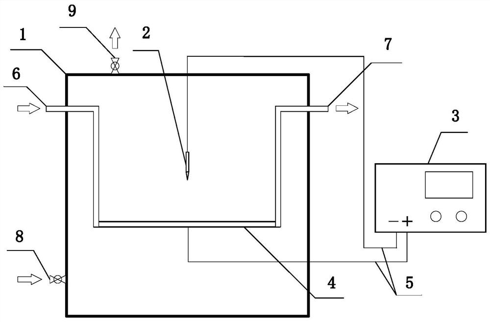
[0026]Such asfigure 1As shown, a device that utilizes ion wind strengthens condensed heat transfer, the main structure includes a vacuum coagulating cavity body 1, provided in the needle tip electrode 2 in the vacuum coagulating cavity 1, a horizontal metal tube 4 vertically disposed with the needle tip electrode 2, connection The water pipe 6 and the water pipe 7 on both ends of the horizontal metal pipe 4, respectively connect the needle tip electrode 2 and the negative pressure high voltage power source 3 of the horizontal metal pipe 4, and the intake valve 8 and the air valve 9 of the vacuum condensed cavity 1, the The needle tip electrode 2 is connected to the negative electrode of the negative pressure high voltage power source 3, and the horizontal metal pipe 4 is connected to the positive electrode of the negative pressure high voltage power source 3, and the tip of the needle electrode 2 points to the horizontal metal tube 4. The vacuum coagulating cavity 1 is a square stru...

Embodiment 2

[0031]A method of using ion-wind-intensified condensation heat transfer, the flow rate is 0.5 l / min, the temperature is 20 ° C (temperature range is 10 to 60 ° C; the flow range is 0.1 L / min ~ 5L / min, the present embodiment is preferably 0.5L. / min, 20 ° C) circulating cooled water flows from the intake pipe 6 of the vacuum condensed cavity 1, flowing out from the water pipe 7; temperature is 110 ° C, the pressure is 0.14 MPa (temperature range 90 ° C ~ 150 ° C; pressure range 0.07 MPA ~ 0.5 MPa, the aerosolic temperature of the present embodiment is 110 ° C, the pressure is 0.14 MPa), from the intake valve 8 of the vacuum coagulating cavity body 1, the air condensed cavity 1 of the air-condensed cavity 1 is only used The remaining gas release after the work. The gaseous working pressure is 0.01 MPa, the temperature is 46 ° C (temperature range is from 30 ° C to 80 ° C; the pressure range is 0.004 MPa ~ 0.05 MPa, the present embodiment is preferably 0.01 MPa, the temperature ...


PUM


Abstract

The invention belongs to the technical field of enhanced condensation heat exchange of thermal power engineering, and particularly relates to a device and method for enhancing condensation heat exchange by utilizing ionic wind. The device mainly comprises a vacuum condensation cavity, a needle point electrode arranged in the vacuum condensation cavity, a horizontal metal pipe perpendicular to the needle point electrode, a water inlet pipe and a water outlet pipe which are connected with the two ends of the horizontal metal pipe, a negative-pressure high-voltage power supply connected with the needle point electrode and the horizontal metal pipe respectively, and an air inlet valve and an air outlet valve which are arranged in the vacuum condensation cavity, wherein the needle point electrode is connected with a negative electrode of a negative-voltage high-voltage power supply, the horizontal metal pipe is connected with a positive electrode of the negative-voltage high-voltage power supply, and the point of the needle point electrode points to the horizontal metal pipe. According to the device, the negative-voltage high-voltage power supply is used for forming high electric field intensity near the needle point electrode, then ionic wind is generated, the migration process of steam towards the condensation wall face is enhanced, and therefore the condensation heat exchange effect is enhanced.

Description

Technical field[0001]In the field of strengthening of thermal energy engineering, the present invention, in particular, to a method and method of using ion-resistant condensed condensation heat transfer.Background technique[0002]Steam coagulation is a common phenomenon that is easily observed in nature, which is widely used in the industry, such as heat pipes, electricity plants in the laptop, and condensed towers. When the temperature of the condensed surface is lower than the steam temperature, steam is condensed on the condensation surface, which is accompanied by quality and energy transfer. Energy is passed from steam to the condensation surface in the form of latent heat, and how to improve heat transfer effects is crucial in industrial applications. For example, if the heat transfer effect of the heat pipe condensed portion in the electronic device can be strengthened, it can significantly reduce the operating temperature of the electronic device, which prevents the electroni...

Claims


Application Information

Patent Timeline
Patent Type & Authority Applications(China)
IPC IPC(8): F28D15/02H05K7/20
CPCF28D15/025H05K7/20336
Inventor 龚政郑怀苏振鹏
Owner WUHAN UNIV
Learn More