Electrical control cabinet

A technology of electrical control cabinet and air outlet, which is applied in electrical components, electrical equipment shell/cabinet/drawer, electrical equipment structural parts, etc. It can ensure the normal and stable entry, alleviate the blockage phenomenon, and improve the heat dissipation efficiency.

Inactive Publication Date: 2021-04-06
张彦生
View PDF6 Cites 12 Cited by
  • Summary
  • Abstract
  • Description
  • Claims
  • Application Information

AI Technical Summary

Problems solved by technology

[0003] Because there are many electrical components inside the electrical control cabinet, it will generate a lot of heat during use. The existing electrical control cabinet has a poor heat dissipation effect. The method of simply flowing hot air through the heat dissipation holes for heat dissipation has low heat dissipation efficiency, and in order to avoid the entry of dust, most of them will install dust-proof nets at the heat dissipation holes to achieve the purpose of dust prevention; but the dust-proof nets do not have the ability to vibrate in time Dust removal function, although the dust-proof net at the air inlet can prevent dust from entering the cabinet during use, but the dust is easy to statically adhere to and accumulate on the dust-proof net, resulting in reduced ventilation efficiency at the air inlet, thereby reducing The heat dissipation efficiency can not meet the needs of use, and the above situation should be improved, so we propose an electrical control cabinet to solve the above problems

Method used


Image

  • Electrical control cabinet
  • Electrical control cabinet
  • Electrical control cabinet

Examples


Embodiment

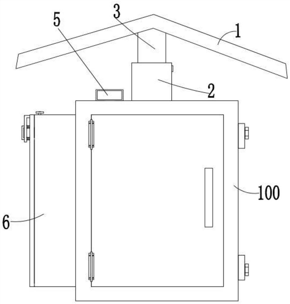
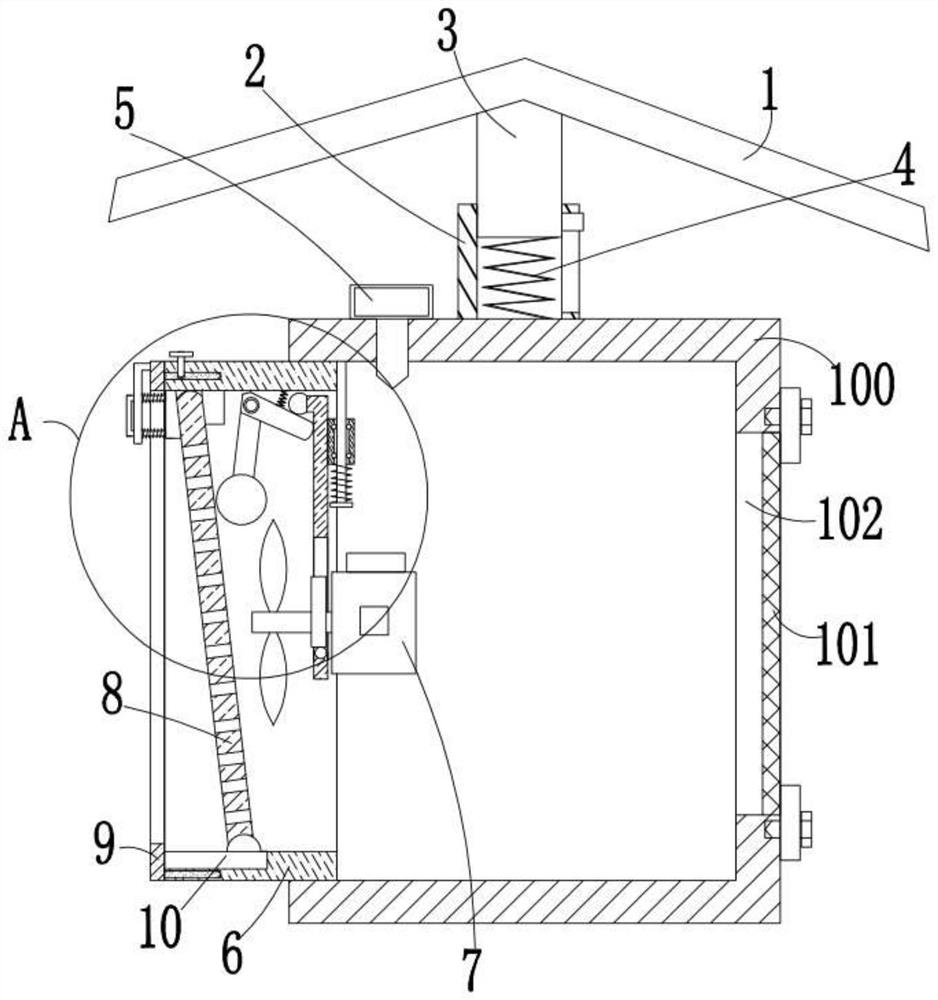
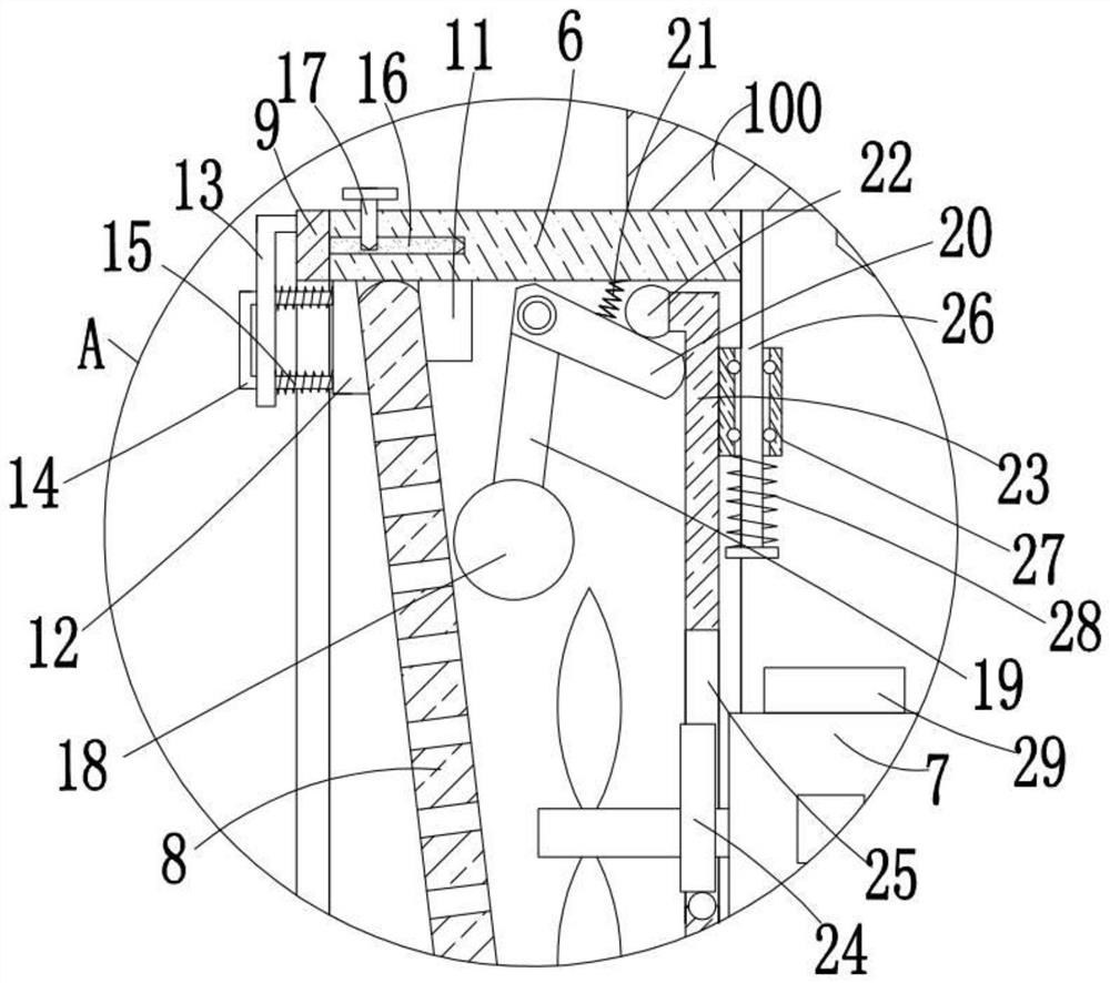
[0026] refer to Figure 1-4, this embodiment proposes an electrical control cabinet, including an electrical control cabinet body 100, an air outlet 102 is opened on the right inner wall of the electrical control cabinet body 100, and a dust-proof net 101 is provided in the air outlet 102 to prevent dust The net 101 is threaded and fixed on the right side of the electrical control cabinet body 100. A V-shaped protective plate 1 is arranged above the electrical control cabinet body 100. A fixed block 3 is fixedly installed on the bottom of the V-shaped protective plate 1. The top of the electrical control cabinet body 100 A rectangular tube 2 is fixedly installed, and the rectangular tube 2 is slidably set on the fixed block 3. A plurality of buffer springs 4 are fixedly installed between the bottom of the fixed block 3 and the top of the electrical control cabinet body 100. The left side of the electrical control cabinet body 100 A back-shaped frame 6 is embedded on the side i...


PUM


Abstract

The invention discloses an electrical control cabinet which comprises an electrical control cabinet body. An air outlet hole is formed in the inner wall of the right side of the electrical control cabinet body, a dustproof net is movably arranged in the air outlet hole in a sleeved mode, the dustproof net is fixed to the right side of the electrical control cabinet body in a threaded mode, and a V-shaped protection plate is arranged above the electrical control cabinet body. The bottom of the V-shaped protection plate is fixedly provided with a fixed block, and the top of the electrical control cabinet body is fixedly provided with a rectangular pipe which sleeves the fixed block in a sliding manner. The electrical control cabinet is reasonable in design, the cooling fan can be automatically started to dissipate heat when the temperature in the electrical control cabinet body is higher than the preset temperature, the heat dissipation efficiency is improved, the dustproof plate can be conveniently and continuously vibrated left and right in the heat dissipation process, and dust particles attached to the right side of the dustproof plate can be effectively vibrated off in cooperation with the inclined arrangement mode of the dustproof plate; the blocking phenomenon is relieved, normal and stable entering of air is guaranteed, the dustproof plate can be taken out to be cleaned, and the use requirement is met.

Description

technical field [0001] The invention relates to the technical field of electrical control cabinets, in particular to an electrical control cabinet. Background technique [0002] Control cabinets usually refer to the metal cabinets used to install switching appliances that control the operation of electrical appliances. Control cabinets are divided into electrical control cabinets, frequency conversion control cabinets, low-voltage control cabinets, high-voltage control cabinets, water pump control cabinets, and power control cabinets according to their functions. , explosion-proof control cabinets, elevator control cabinets, PLC control cabinets, fire control cabinets and brick machine control cabinets, etc. Among them, the electrical control cabinet refers to a complete set of control cabinets, which can realize the electrical switch control of the motor. [0003] Because there are many electrical components inside the electrical control cabinet, it will generate a lot of h...

Claims


Application Information

Patent Timeline
Patent Type & Authority Applications(China)
IPC IPC(8): H05K5/02H05K7/20B01D46/10B01D46/42
CPCH05K5/0217H05K7/20209H05K7/20172H05K7/20181B01D46/10B01D46/76
Inventor 张彦生
Owner 张彦生
Why Eureka
Try Eureka