A corn kernel peeling device for corn threshing

A corn threshing and stripping device technology, applied in threshing equipment, applications, agriculture, etc., can solve the problem of inability to thresh multiple corns

Active Publication Date: 2021-09-07
黑龙江商博士农业发展有限公司
View PDF1 Cites 0 Cited by
  • Summary
  • Abstract
  • Description
  • Claims
  • Application Information

AI Technical Summary

Problems solved by technology

But the invention can't thresh multiple corns quickly

Method used


Image

  • A corn kernel peeling device for corn threshing
  • A corn kernel peeling device for corn threshing
  • A corn kernel peeling device for corn threshing

Examples


specific Embodiment approach 1

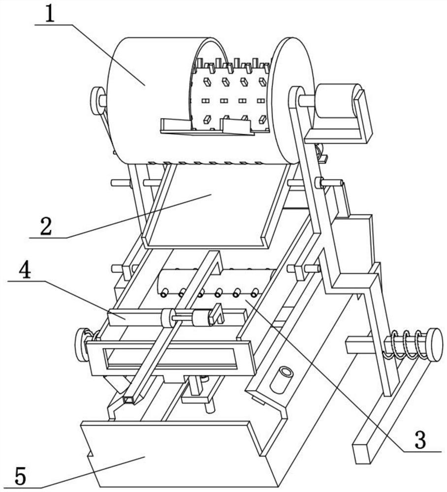
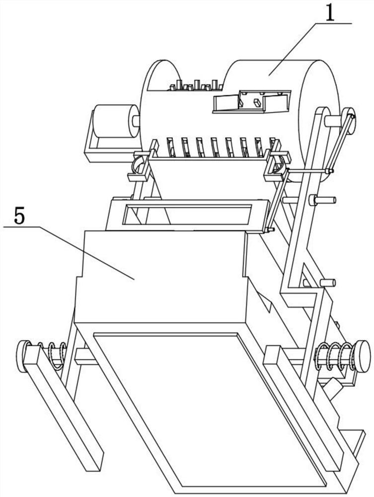
[0031] Combine below Figure 1-9 To illustrate this embodiment, the present invention relates to the field of corn threshing, more specifically, a corn kernel peeling device for corn threshing, including a peeling cylinder 1, a feeding slide 101, a short shaft 102, a pulp discharging slide 103, and a grain leakage hole 104, drum 106 and stripping column 107, the present invention can quickly thresh multiple corns.

[0032] A plurality of peeling columns 107 are fixedly connected to the outer peripheral surface of the rotating drum 106, and short shafts 102 are fixedly connected to the left and right sides of the rotating drum 106. The rotating drum 106 is located in the peeling drum 1, and the two short shafts 102 are connected in rotation In the left and right parts of the stripping cylinder 1, the stripping cylinder 1, the short shaft 102 and the rotating cylinder 106 are coaxially arranged, and a plurality of particle leakage holes 104 are evenly distributed on the lower si...

specific Embodiment approach 2

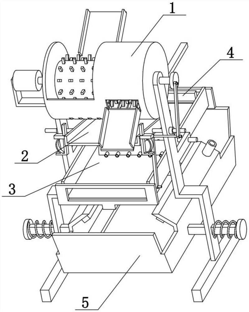
[0034] Combine below Figure 1-9 To illustrate this embodiment, the corn kernel peeling device for corn threshing also includes an inclined slide plate 2, a motor I201, a side shaft I202 and a bracket 203, and the left and right sides of the inclined slide plate 2 are fixedly connected with a side shaft I202, and the two sides Axis 1202 is rotatably connected to the middle of the two brackets 203, the inclined slide plate 2 is located below the stripping cylinder 1, and the two short shafts 102 are rotatably connected to the upper parts of the two brackets 203, and the bracket 203 on the right side is fixedly connected with a motor I201, the output shaft of the motor I201 is fixedly connected to the short shaft 102 at the right end. The motor I201 is used to drive the two short shafts 102 and the drum 106 to rotate at a high speed, and then the corn kernels are peeled off from the corn. Inclined slide plate 2 is used to accept the corn kernel that leaks from hole 104, and inc...

specific Embodiment approach 3

[0036] Combine below Figure 1-9To illustrate this embodiment, the corn kernel peeling device for corn threshing also includes a turntable 105, a protruding shaft 208, and a hinged rod I209. Shaft 208, the lower end of hinged rod I209 is rotatably connected on the protruding shaft 208. The motor I201 drives the two short shafts 102 and the rotating drum 106 to rotate and also drives the turntable 105 to rotate. When the turntable 105 rotates, the hinged rod I209 drives the inclined slide 2 to continuously swing up and down, thereby preventing corn kernels from accumulating on the inclined slide 2, which is convenient Corn kernels fall.


PUM


Abstract

The invention relates to the field of corn threshing, more specifically a corn kernel peeling device for corn threshing, including a peeling cylinder, a feeding slide, a short shaft, a pulp discharging slide, a leaking hole, a rotating cylinder and a peeling column. The invention allows rapid threshing of multiple corns. A plurality of peeling columns are fixedly connected to the outer peripheral surface of the rotating drum, short shafts are fixedly connected to the left and right sides of the rotating drum, the rotating drum is located in the peeling drum, and the two short shafts are respectively connected to the left and right parts of the peeling drum in rotation. , the peeling cylinder, the short shaft and the rotating cylinder are coaxially arranged, and the lower side of the peeling cylinder is evenly distributed with a plurality of leakage holes, the upper side of the peeling cylinder is provided with a feeding slide plate, and the lower side of the peeling cylinder is provided with a pulp discharge slide plate. The corn grain peeling device for corn threshing also includes an inclined slide plate, a motor I, a side shaft I and a support, and the left and right sides of the inclined slide plate are fixedly connected with side shafts I, and the two side shafts I are respectively rotatably connected to two In the middle part of the support, the inclined slide plate is located under the stripping cylinder.

Description

technical field [0001] The invention relates to the field of corn threshing, in particular to a corn kernel peeling device for corn threshing. Background technique [0002] The application number is CN201810397579.8, which discloses a new type of corn thresher. The invention relates to the technical field of modern agricultural equipment, and discloses a new type of corn thresher, including a corn thresher. The top of the corn thresher is provided with a feed There is a rotating shaft I in the middle of the feed inlet, and one end of the rotating shaft I passes through the inside of the bearing I and extends to the outside of one side of the corn thresher, and the outer wall of the bearing I is fixedly installed inside the side of the corn thresher The outer wall of the rotating shaft I is fixed with a threshing sheet, the other end of the rotating shaft I passes through the inside of the bearing II and extends to the outside of the other side, and the outer wall of the bear...

Claims


Application Information

Patent Timeline
Patent Type & Authority Patents(China)
IPC IPC(8): A01F11/06A01F12/18A01F12/44
CPCA01F11/06A01F12/18A01F12/44A01F12/446
Inventor 张铁强景尚友王翊王慧王仁杰姜丽静肖洪梅谢丽华
Owner 黑龙江商博士农业发展有限公司
Why Eureka
Try Eureka