Corn threshing device

A corn threshing and corn kernel technology, applied in the field of agricultural machinery, can solve problems such as hand injury, corn kernel stress, food waste, etc., to achieve the effect of ensuring quality, reducing labor intensity, and improving production efficiency

Inactive Publication Date: 2022-04-12
董玉龙
View PDF0 Cites 0 Cited by
  • Summary
  • Abstract
  • Description
  • Claims
  • Application Information

AI Technical Summary

Problems solved by technology

[0002] Corn has high nutritional value and is an important food crop in my country. Corn cobs need to be threshed after they are harvested. Traditional manual threshing has a large workload, low efficiency, and will cause damage to the hands. It is the first choice to use machinery to thresh corn cobs. The thresher is a machine for threshing dried corn cobs, mostly of the axial flow drum type, which is mainly composed of a drum, a concave plate sieve, a feeding hopper, a screw guide rod, etc. Axial-flow threshing, the corn cobs enter the drum through the feeding hopper, and the corn cobs are threshed under the impact of the high-speed rotary drum and the interaction of the corn ear, the drum and the concave plate, but the threshing part and the concave plate sieve rub the corn ear together, it will It will cause great stress to the corn kernels, and it will inevitably cause damage to the surface of the corn kernels while threshing, and even directly crush the corn kernels, which will affect the quality of the corn and cause food waste. It is necessary to provide a corn threshing The device improves the production efficiency while ensuring the quality of corn cobs after threshing

Method used


Image

  • Corn threshing device
  • Corn threshing device
  • Corn threshing device

Examples


Embodiment Construction

[0028] The materials, methods, and instruments used in the following examples are not specified, and are all conventional materials, methods, and instruments in the art, and those skilled in the art can be obtained by commercial channels.

[0029] In the following description, in the following description, it is to be described, the term "center", "longitudinal", "landscape", "upper", "lower", "front", "post", "left", "right", The orientation relationship between "top", "bottom", "inside", "outside" and "vertical", etc. are based on the orientation or positional relationship shown in the drawings, only for convenience of description of the present invention and simplified description. Instead of indicating or implying that the device or component must have a specific orientation, constructing and operating in a particular direction, and thus is not to be construed as limiting the invention.

[0030] In the following description of the invention, it is to be explained, unless other...


PUM


Abstract

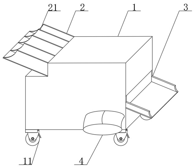
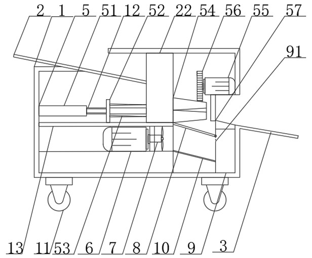
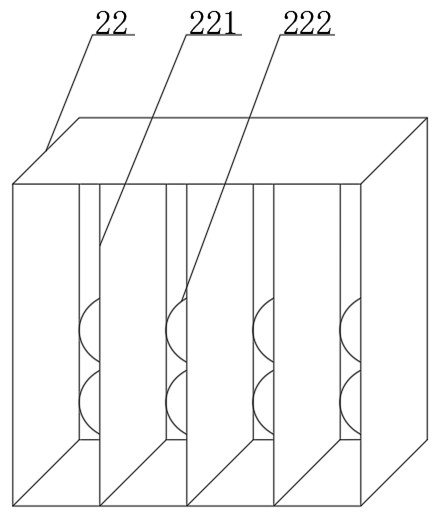
The invention belongs to the technical field of agricultural machinery, and particularly relates to a corn threshing device which comprises a corn threshing vehicle, a feeding plate is installed at the top end of the corn threshing vehicle, a corncob discharging port is formed in the side face of the corn threshing vehicle, and a corn kernel discharging port is formed in the side face of the long edge of the corn threshing vehicle. A discharging groove is formed in the position, located at the bottom end of the feeding plate, in the corn threshing vehicle, a supporting plate is installed in the corn threshing vehicle, a propelling threshing mechanism is installed on the upper end face of the supporting plate, the second motor is installed on the lower end face of the supporting plate, and a blowing fan is installed on a driving shaft of the second motor. A filter plate is installed at the position, close to the corncob discharging port, in the corn threshing vehicle, the arranged discharging groove is matched with the propelling threshing mechanism to achieve rapid threshing of corn cobs, production efficiency is improved, labor intensity of people is relieved, compared with an existing corn thresher, threshed corn kernels cannot be damaged, and the corn thresher is convenient to use and popularize. And the quality of the corn is ensured.

Description

Technical field [0001] The present invention belongs to the technical field of agricultural machinery, and in particular to a corn threshing device. Background technique [0002] The corn has a high nutritional value. It is an important food crop in my country. After the corn rod is closed, it needs to be thilled. The traditional hand-degree of handmade has a large amount of work, and the efficiency is low. It will cause damage to the hand, and the corn rod is taken into the preferred, corn. The thresher is a mechanical mechanical to dry after drying the corn rod, which is more axial roller type, which is mainly composed of a roller, a diaphragm screen, a feed hopper, a spiral guide, and a cut-to-pending shaft end. The axial flow is removed, and the corn rod enters the drum through the feed hopper, and the corn rod is thiled under the impact of the high-speed rotary roller, the roller, the drum, and the recess, but the thorny and the recess screen are common to the corn fruit, wi...

Claims


Application Information

Patent Timeline
Patent Type & Authority Applications(China)
IPC IPC(8): A01F11/06A01F12/10A01F12/22A01F12/44A01F12/46A01F12/58
Inventor 董玉龙
Owner 董玉龙
Why Eureka
Try Eureka