Chemical reaction kettle with air pressure stabilizing structure

A technology for stabilizing structures and chemical reactions, applied in chemical/physical/physical chemical fixed reactors, chemical instruments and methods, chemical/physical processes, etc., can solve the problems of poor mixing effect, long time consumption, and insufficient reaction of chemical raw materials and other problems, to improve the mixing effect, shorten the time, and avoid the effect of blocking the catheter

Inactive Publication Date: 2021-04-09
刘茂林
View PDF0 Cites 1 Cited by
  • Summary
  • Abstract
  • Description
  • Claims
  • Application Information

AI Technical Summary

Problems solved by technology

[0003] When the currently used chemical reaction kettle is mixing chemical raw materials, if the mixed chemical raw materials are granular and liquid, during the mixing process, part of the granular chemical raw materials will precipitate at the lower end of the reaction kettle and block the discharge structure on the reaction kettle. In the middle, the chemical raw materials cannot fully react, and in the mixing process, if two liquid chemical raw materials are mixed, it is difficult for the chemical raw materials located at the bottom to quickly mix with the chemical raw materials located at the top, and it takes a long time, and When mixing, most of the chemical raw materials are directly put into the interior of the reactor, and the various chemical raw materials are mixed at one time, and the mixing effect is poor.

Method used


Image

  • Chemical reaction kettle with air pressure stabilizing structure
  • Chemical reaction kettle with air pressure stabilizing structure
  • Chemical reaction kettle with air pressure stabilizing structure

Examples


Embodiment Construction

[0026] In order to make the technical means, creative features, goals and effects achieved by the present invention easy to understand, the present invention will be further described below in conjunction with specific embodiments.

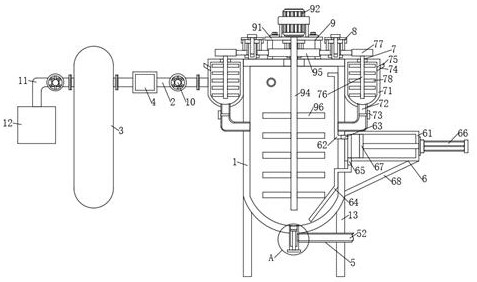
[0027] like Figure 1-Figure 7 As shown, a chemical reaction kettle with a stable air pressure structure according to the present invention includes a reactor main body 1, and a first fixed pipe 2 is fixedly connected to the side wall of one side of the reaction kettle main body 1. One end of the first fixed pipe 2 away from the reactor main body 1 is fixedly connected with an air storage tank 3, and the air storage tank 3 is fixedly connected with an air compressor 12 through a second fixed pipe 11, and the first fixed pipe 2 is fixedly connected with A gas regulator 4 and a pneumatic valve 10 are arranged, and observation windows 14 are fixedly connected to the side walls on both sides of the front side of the reaction kettle main body 1, and th...


PUM


Abstract

The invention relates to the field of chemical reaction kettles, and in particular, relates to a chemical reaction kettle with an air pressure stabilizing structure, wherein the chemical reaction kettle comprises a reaction kettle main body, a first fixing pipe is fixedly connected to the side wall of the back face of one side of the reaction kettle main body, and a gas storage tank is fixedly connected to one end, away from the reaction kettle main body, of the first fixing pipe; the gas storage tank is fixedly connected with an air compressor through a second fixing pipe; a gas pressure stabilizer and a pneumatic valve are fixedly connected to the first fixing pipe; a liquid outlet mechanism is mounted in the middle of the lower end of the reaction kettle main body; supporting columns are fixedly connected to the outer walls of the four corners of the lower end of the reaction kettle main body, and a mixing mechanism is mounted in the middle of the upper end of the reaction kettle main body. The liquid outlet mechanism is arranged at the lower end of the reaction kettle, and the upper end of a first piston of the liquid outlet mechanism is flush with the lower end in the reaction kettle main body, so that granular chemical raw materials in the reaction kettle are difficult to enter a liquid guide pipe, and the liquid guide pipe is prevented from being blocked by the granular chemical raw materials; and the mixing reaction between the granular chemical raw materials and the liquid chemical raw materials is facilitated.

Description

technical field [0001] The invention relates to the field of chemical reaction kettles, in particular to a chemical reaction kettle with an air pressure stable structure. Background technique [0002] The chemical reaction kettle is one of the main devices used in the manufacture of chemical products. It is used for the mixed reaction of various chemical raw materials and is also a common chemical device. [0003] When the currently used chemical reaction kettle is mixing chemical raw materials, if the mixed chemical raw materials are granular and liquid, during the mixing process, part of the granular chemical raw materials will precipitate at the lower end of the reaction kettle and block the discharge structure on the reaction kettle. In the middle, the chemical raw materials cannot fully react, and in the mixing process, if two liquid chemical raw materials are mixed, it is difficult for the chemical raw materials located at the bottom to quickly mix with the chemical ra...

Claims


Application Information

Patent Timeline
IPC IPC(8): B01J19/18B01J19/00B01J4/00B01F13/10
CPCB01J19/18B01J19/0053B01J19/0066B01J4/001B01F33/813
Inventor 刘茂林
Owner 刘茂林
Why Eureka
Try Eureka