Combined machining anti-static workbench

A mechanical processing and workbench technology, which is applied in workbenches, metal processing equipment, metal processing machinery parts, etc., can solve the problems of no workbench lifting adjustment, inconvenient storage of processed objects, etc., and achieves simple structure, convenient storage, and convenient use. Effect

Active Publication Date: 2021-04-09
西安钜宸科技有限公司
View PDF7 Cites 1 Cited by
  • Summary
  • Abstract
  • Description
  • Claims
  • Application Information

AI Technical Summary

Problems solved by technology

[0004] The purpose of the present invention is to solve the shortcomings of the existing combined anti-static workbench for mechanical processing. When in use, there is no function of lifting and adjusting the workbench, and it is not convenient to store the processed objects. A combined type is proposed. Machining anti-static workbench

Method used


Image

  • Combined machining anti-static workbench
  • Combined machining anti-static workbench
  • Combined machining anti-static workbench

Examples


Embodiment 1

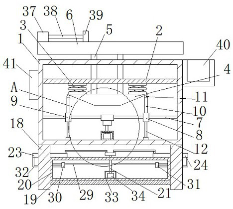
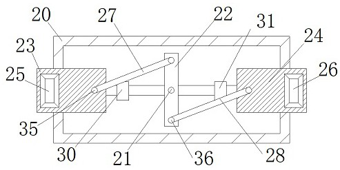
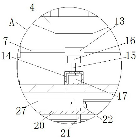
[0028] refer to Figure 1-5 , a combined anti-static workbench for mechanical processing, including an adjustment box 1, a support top plate 2 is fixedly installed in the adjustment box 1, two return springs 3 are fixedly connected to the bottom of the support top plate 2, and one end of the two return springs 3 is fixed The same inclined top plate 4 is connected, and two push rods 5 are fixedly installed on the inclined top plate 4. One end of the two push rods 5 extends through the support top plate 2 to the top of the adjustment box 1, and one end of the two push rods 5 is fixed. The same workbench body 6 is connected, and the adjustment box 1 is rotationally connected with a driving screw 7, the driving screw 7 is fixedly connected with a worm rod 13, and the driving screw 7 is threaded with a first threaded plate 8 and a second screw thread. Plate 9, the first threaded plate 8 and the second threaded plate 9 are all fixedly connected with a drag column 10, and one end of ...

Embodiment 2

[0039] refer to Figure 1-5 , a combined mechanical processing anti-static workbench, including an adjustment box 1, a support top plate 2 is welded and installed in the adjustment box 1, two return springs 3 are welded and connected to the bottom of the support top plate 2, and one end of the two return springs 3 is welded The same sloping top plate 4 is connected, and two push rods 5 are welded on the sloping top plate 4, and one end of the two push rods 5 extends through the support top plate 2 to the top of the adjustment box 1, and one end of the two push rods 5 is welded The same workbench body 6 is connected, and the adjustment box 1 is rotationally connected with a driving screw 7. The driving screw 7 is welded and connected with a worm rod 13, and the driving screw 7 is threaded with a first threaded plate 8 and a second screw thread. Plate 9, the first threaded plate 8 and the second threaded plate 9 are all welded with a drag column 10, and one end of the two drag c...


PUM


Abstract

The invention belongs to the technical field of liftable anti-static workbenches, particularly relates to a combined machining anti-static workbench, and provides the following scheme for solving the problems that when an existing combined machining anti-static workbench is used, the workbench does not have the lifting adjusting function, and machined objects are inconvenient to store. The combined machining anti-static workbench comprises an adjusting box, a supporting top plate is fixedly installed in the adjusting box, two reset springs are fixedly connected to the bottom of the supporting top plate, one ends of the two reset springs are fixedly connected with the same inclined top plate, two push rods are fixedly installed on the inclined top plate, one ends of the two push rods penetrate through the supporting top plate and extend to the top of the adjusting box, one ends of the two push rods are fixedly connected with the same workbench body, and a driving lead screw is rotationally connected into the adjusting box. The workbench is simple in structure, the workbench body can be lifted, machined objects can be stored conveniently, and people can use the workbench conveniently.

Description

technical field [0001] The invention relates to the technical field of liftable antistatic workbench, in particular to a combined antistatic workbench for mechanical processing. Background technique [0002] Static electricity is a charge in a static state or a charge that does not flow (a charge that flows forms a current). Static electricity is formed when charges accumulate on an object or surface, and charges are divided into positive charges and negative charges, that is to say, static electricity is also divided into two types, namely positive static electricity and negative static electricity. Positive static electricity is formed when positive charges gather on an object, and negative static electricity is formed when negative charges gather on an object; static electricity is an objective natural phenomenon that can be produced in many ways, such as contact, Friction, peeling, etc. Electrostatic protection technology, such as electrostatic hazards in the electroni...

Claims


Application Information

Patent Timeline
Patent Type & Authority Applications(China)
IPC IPC(8): B23Q1/25B23Q11/00B25H1/16B25H1/00
CPCB23Q1/25B23Q11/0042B25H1/16B25H1/00
Inventor 孙桂玉
Owner 西安钜宸科技有限公司
Why Eureka
Try Eureka