
Bill binding clamping plate

A splint and bill technology, applied in binding and other directions, can solve the problems of easy deformation and scattering of secondary binding, unstable fixation, and improper clamping, and achieve the effect of overcoming unstable fixation, firm fixation, and firm credentials.

Pending Publication Date: 2021-04-09
GUILIN NORMAL COLLEGE
View PDF0 Cites 0 Cited by
  • Summary
  • Abstract
  • Description
  • Claims
  • Application Information

AI Technical Summary

Problems solved by technology

[0007] The beneficial effects of the present invention are: by setting the original bottom plate, the cover plate, and the pressing part, it is possible to overcome the problem that the bills are often inclined during the clamping process, the clamping is not correct, or the bills are easily dropped during the handling process, and the bills are lost, and The operation of binding and threading the bills directly in the bill splint is realized, which saves the user's time, provides convenience for the user, and prevents irreparable losses to the user. Moreover, the three binding holes can be completed continuously at one time, which overcomes the pain points of the existing fixing method, such as unstable fixation and easy deformation and scattering of secondary binding, and using the present invention, the punching link and thread binding link of voucher binding are completed on the splint at one time, It can effectively ensure that the bound vouchers are firm, neat and beautiful, and improve work efficiency

Method used


Image

  • Bill binding clamping plate
  • Bill binding clamping plate
  • Bill binding clamping plate

Examples


Embodiment 1

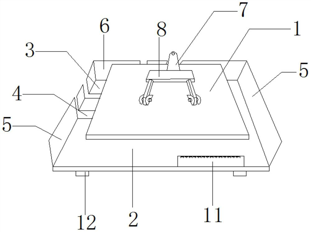
[0040] Such as figure 1 As shown, a bill binding splint includes a base plate original and a cover plate 1, the cover plate 1 is arranged on the upper part of the base plate original, and the base plate original is provided with a clamp for pressing the cover plate 1 onto it. Compression piece.

[0041] It should be understood that the length of the cover plate 1 is smaller than the length of the original bottom plate.

[0042] Specifically, the bill is placed on the original bottom plate, and the cover plate 1 is pressed tightly by the pressing member to prevent the cover plate 1 from moving freely.

[0043] In the above-mentioned embodiment, by setting the original bottom plate, cover plate, and pressing parts, it is possible to overcome the problems that the bills are often inclined during the clamping process, the clamping is not correct, or the bills are easily dropped during the transportation process, and the bills are lost. The operation of binding and threading the ...

Embodiment 2

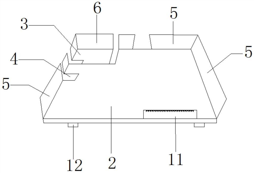
[0045] Such as Figures 1 to 2 As shown, a bill binding splint includes a base plate original and a cover plate 1, the cover plate 1 is arranged on the upper part of the base plate original, and the base plate original is provided with a clamp for pressing the cover plate 1 onto it. Compression piece;

[0046]The original bottom plate includes a first bottom plate 2 and a second bottom plate 3, the two sides and one end of the first bottom plate 2 are respectively vertically provided with a first blocking piece 5, and one side of the first bottom plate 2 is provided with an extension To the side end of the side and through the first notch 4 of the first blocking piece 5 on the side, the first notch 4 is used for the passage of the binding thread; a corner of the first bottom plate 2 is provided with a gap, and the first notch 4 The second bottom plate 3 is arranged horizontally, and is detachably mounted on the notch, and the side of the second bottom plate 3 close to the not...

Embodiment 3

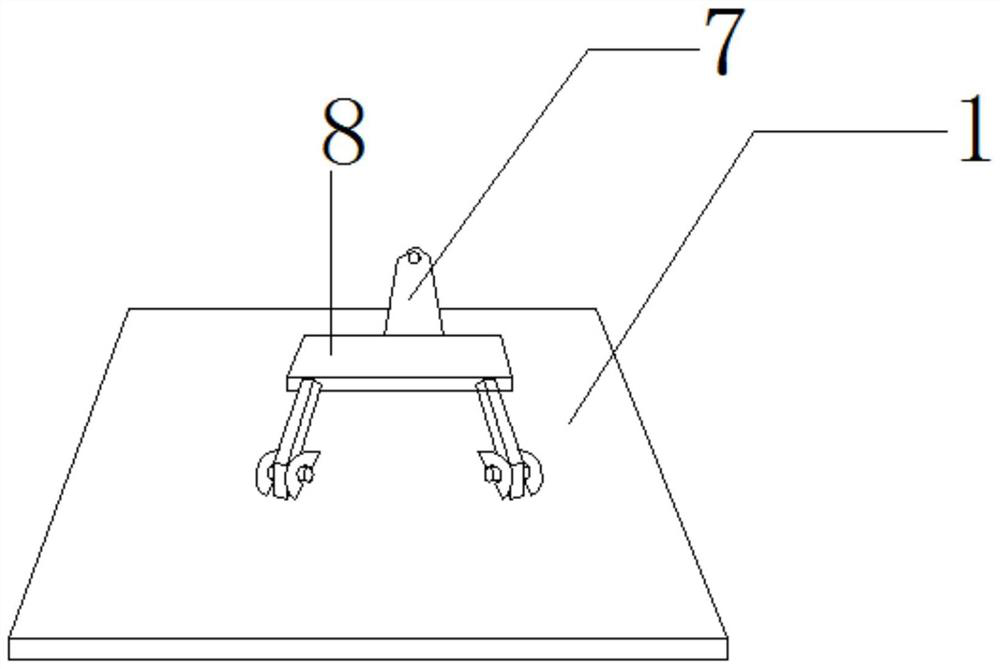
[0053] Such as figure 1 , image 3 with Figure 4 As shown, a bill binding splint includes a base plate original and a cover plate 1, the cover plate 1 is arranged on the upper part of the base plate original, and the base plate original is provided with a clamp for pressing the cover plate 1 onto it. Compression piece;

[0054] The pressing part includes a clamping element 7 and a pressing block 8, one end of the clamping element 7 is rotatably mounted on the base plate element, and the other end is fixedly connected to one end of the pressing block 8, and the pressing block The other end of 8 is provided with a plurality of strip-shaped pressure rollers, and when the clamping element 7 rotates until the pressure block 8 is close to the cover plate 1, the pressure rollers are detachably connected to the cover plate 1 .

[0055] Preferably, the clamping element 7 can be a clip.

[0056] It should be understood that the clamping element 7 uses two springs to increase the a...


PUM


Abstract

The invention provides a bill binding clamping plate which comprises a bottom plate original part and a cover plate. The cover plate is arranged on the upper portion of the bottom plate original part, and a pressing part used for pressing the cover plate on the bottom plate original part is arranged on the bottom plate original part. By means of the bill binding clamping plate, the problem that bills are prone to inclination and improper clamping in the clamping process or prone to falling off in the carrying process, and consequently the bills are lost can be solved, the bills can be directly bound and threaded in the bill binding clamping plate, the time of a user is saved, convenience is brought to the user, and the irretrievable loss to the user is prevented; meanwhile, a clamping plate fixing manner is adopted, fixing is firm, three binding holes can be continuously completed at a time, and the problems that according to an existing fixing method, fixing is not stable, and deformation and scattering are prone to being caused during secondary binding are solved; and by means of the bill binding clamping plate, the punching link and the thread binding link of voucher binding are completed on the clamping plate at a time, it can be effectively guaranteed that bound vouchers are firm, tidy and attractive, and the working efficiency is improved.

Description

technical field [0001] The invention mainly relates to the technical field of office supplies, in particular to a bill binding splint. Background technique [0002] Since various financial bills and vouchers are important archive materials, there are corresponding legal regulations on how to keep them, and the binding of vouchers needs to comply with the corresponding regulations. [0003] When binding vouchers, it is necessary to punch holes in the vouchers sorted into books. There are three commonly used punching methods. The first type, the three-hole triangle type, punches three holes in a triangular shape on the upper left corner of the voucher, and uses thread binding; the second type, the straight three-hole type, punches three holes side by side in a vertical line on the left side of the voucher, using Binding by wire binding; the third type, double-hole type, punches 2 vertical holes on the left side of the certificate, and binds by hot-melt glue. The three metho...

Claims


Application Information

Patent Timeline
IPC IPC(8): B42B5/02B42B2/02
CPCB42B2/02B42B5/02
Inventor 陈晓光吕颖杨占坡
Owner GUILIN NORMAL COLLEGE
Learn More