Pile cutting device and pile cutting method

A cutting pile, square head technology, applied in the cutting loop and other directions, can solve the problems of blade jumping, partial pile, low quality cost, etc., to improve the cutting precision, ensure the quality of cutting pile, and reduce the effect of friction coefficient.

Pending Publication Date: 2021-04-09
江阴唯尔维朵科技有限公司
View PDF0 Cites 2 Cited by
  • Summary
  • Abstract
  • Description
  • Claims
  • Application Information

AI Technical Summary

Benefits of technology

The technical effect of this patented technology reduces the amount of heat generated by each component during operation compared with traditional methods like saw blades or sandpaper grinding machines that use rubber bands for holding tools together. This results in less wear on components while maintaining their precision.

Problems solved by technology

This patented technical problem addressed by this patents relates to improving the accuracy with controlling the movement or position (velocity) of an object being processed when rotating a tool called a lattice saw through materials like foam rubber. Specifically, current methods involve setting a knob clip before mounting onto the saw's frame, but if there are any issues such as excessive pressure between the knot and the edge of the material being worked upon, these factors can lead to damage to either the device itself or the workpiece being machined due to heat buildup caused by friction generated while processing the material.

Method used


Image

  • Pile cutting device and pile cutting method
  • Pile cutting device and pile cutting method
  • Pile cutting device and pile cutting method

Examples


Embodiment Construction

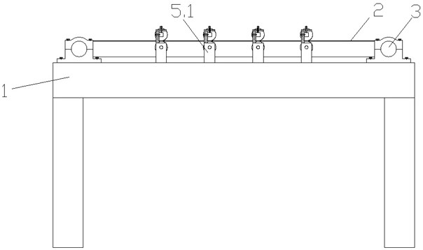
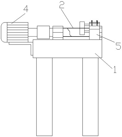
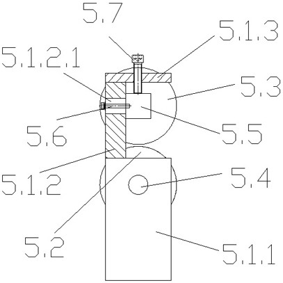
[0020] see Figure 1-4 , the invention relates to a velvet cutting device, comprising a frame 1, an annular cutter 2 and two rotating rollers 3, the two rotating rollers 3 are arranged at both ends of the frame 1 through bearing seats, and the motor 4 is connected by a coupling A rotating roller 3 drives the rotating roller 3 to rotate. The annular cutting knife 2 is sleeved on the two rotating rollers 3. The frame 1 is provided with a plurality of clamping knife assemblies 5, and the clamping knife assembly 5 includes The tool feeder 5.1, the lower roller 5.2, the upper roller 5.3, the lower connecting shaft 5.4 and the upper connecting shaft 5.5, the cutter feeder 5.1 is fixed on the frame 1, and the cutter feeder 5.1 is located on the front side of the ring cutter 2 , the tool feeder 5.1 includes a fixed block 5.1.1, a side plate 5.1.2 and an upper connecting plate 5.1.3 arranged in sequence, one end of the lower connecting shaft 5.4 is connected to the fixed block 5.1.1, a...


PUM


Abstract

The invention relates to a pile cutting device that comprises a machine frame, an annular cutting knife and two rotating rollers, wherein a plurality of knife clamping assemblies are arranged on the machine frame; each knife clamping assembly comprises a knife feeding base, a lower idler wheel, an upper idler wheel, a lower connecting shaft and an upper connecting shaft; the knife feeding base is fixed to the machine frame and located on the front side of the annular cutting knife; the knife feeding base comprises a fixed block, a side plate and an upper connecting plate which are sequentially arranged; one end of the lower connecting shaft is connected with the fixed block, the other end of the lower connecting shaft is rotationally connected with the lower idler wheel, one end of the upper connecting shaft is fixed with the side plate through a bolt, the other end of the upper connecting shaft is rotationally connected with the upper idler wheel, and the annular cutting knife is clamped between the lower idler wheel and the upper idler wheel. According to the pile cutting device, the annular cutting knife is clamped through the upper idler wheel and the lower idler wheel, and both the upper idler wheel and the lower idler wheel are in rolling friction with the annular cutting knife, so that a friction coefficient is greatly reduced, a blade is prevented from being overheated, pile cutting is more stable, the precision error of the pile cutting knife is reduced to 0-5 silk, the pile cutting precision is improved by three times, and the pile cutting quality is guaranteed.

Description


Claims


Application Information

Patent Timeline
Owner 江阴唯尔维朵科技有限公司
Why Eureka
Try Eureka