Bending machine workbench precision bidirectional mechanical deflection compensation device and fabrication method thereof

A compensation device and worktable technology, applied in the field of bending machines, can solve the problems of accumulated errors, poor straightness of workpieces, and poor consistency of bending angles of workpieces in the entire length, so as to achieve convenient operation, improve bending accuracy, and reduce manufacturing costs. Effect

Pending Publication Date: 2019-02-15
ANHUI LIYUAN NUMERICAL CONTROL CUTTING TOOL & PATTERNS MFG
View PDF11 Cites 6 Cited by
  • Summary
  • Abstract
  • Description
  • Claims
  • Application Information

AI Technical Summary

Problems solved by technology

[0006] In view of the split structure of the inclined block or wedge of the compensation device in the prior art, it is easy to cause cumulative errors, and the machining accuracy cannot be guaranteed; and it can only be adjusted in the horizontal direction, and the vertical adjustment cannot be realized, resulting in bending of the workpiece of the sheet metal The problem of poor consistency of the entire length of the angle and poor straightness of the workpiece, the purpose of the present invention is to provide a precision two-way mechanical deflection compensation device for the bending machine workbench. Accumulate errors to match the deflection compensation amount of the workpiece with the actual deflection deformation of the workpiece to ensure the consistency of the bending angle of the workpiece and the straightness of the workpiece

Method used


Image

  • Bending machine workbench precision bidirectional mechanical deflection compensation device and fabrication method thereof
  • Bending machine workbench precision bidirectional mechanical deflection compensation device and fabrication method thereof
  • Bending machine workbench precision bidirectional mechanical deflection compensation device and fabrication method thereof

Examples


Embodiment 1

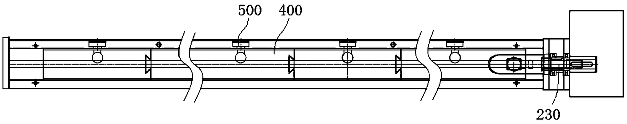
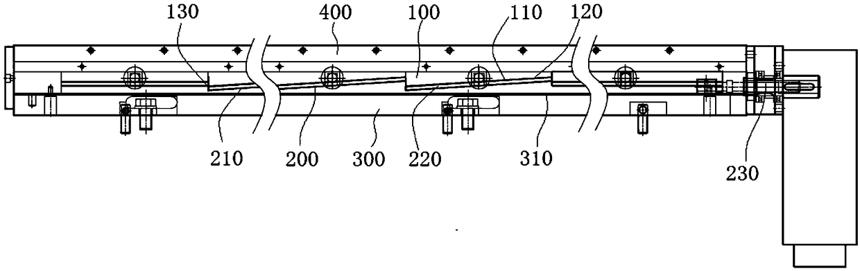
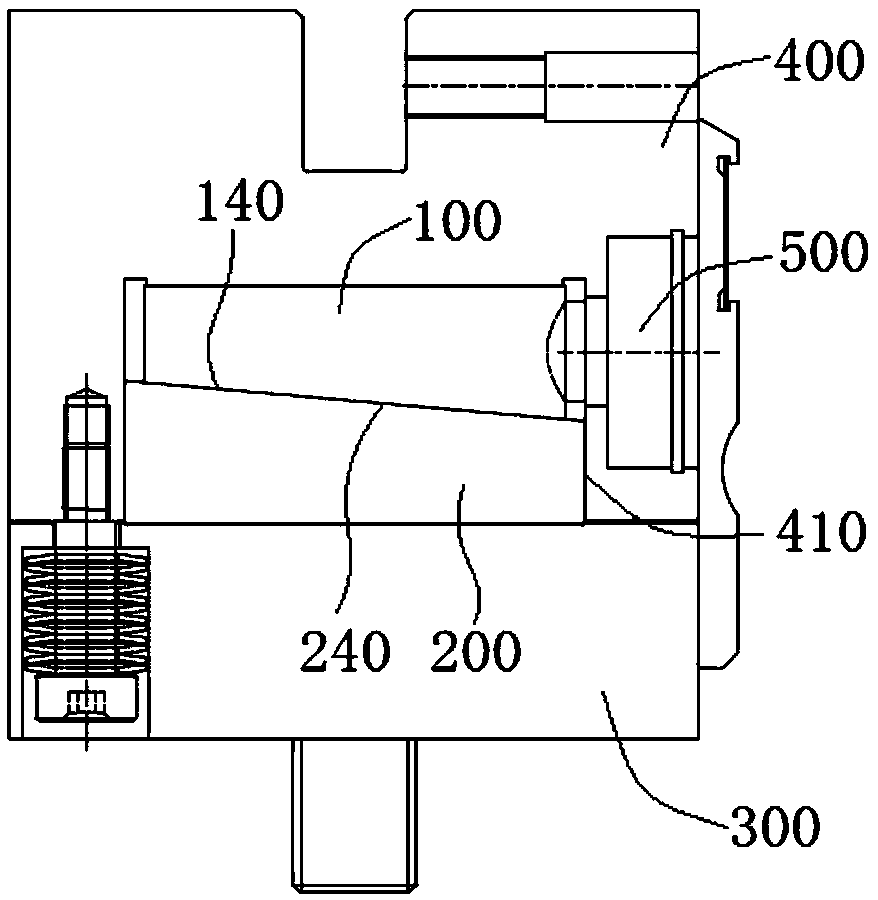
[0047] Please refer to Figure 1 to Figure 3 , The precision two-way mechanical deflection compensation device of the worktable of the bending machine, including the base 300, the cover 400, the upper inclined plate 100, the lower inclined plate 200 and the adjustment mechanism, the upper inclined plate 100 and the lower inclined plate 200 are made of the same material, and are made of high The strength steel is processed.

[0048] The upper inclined plate 100 is divided into several sections, the lower surface 110 is provided with a first longitudinal inclined surface 120 facing the longitudinal direction, the lower inclined plate 200 is an integral structure, and the upper surface 210 of the lower inclined plate 200 is provided with a first longitudinal inclined surface 120 to cooperate with The second longitudinal slope 220, the slopes of the first longitudinal slope 120 and the second longitudinal slope 220 are reduced from a large slope Kj to a small slope Ki from the middle...

Embodiment 2

[0054] The manufacturing method of the precision bidirectional mechanical deflection compensation device for the worktable of the bending machine of the present invention includes the steps:

[0055] S101. Select two plates of the same high-strength steel material, 45# carbon steel chemical composition: C content is 0.50%; Si content is 0.2%; Mn content is 0.5%; Cr content is less than or equal to 0.25%; Ni content is less than or equal to 0.30%; Cu The content is less than or equal to 0.25%, and the rest is Fe.

[0056] S102. On the CNC machine tool, determine one end of the upper inclined plate 100 as the starting point of machining, and use the vertical surface to machine the first inclined surface 120 of the upper inclined plate 100, where the amount of cutting per time L1=[W(C) / W(Si )]*0.1=0.5 / 0.2*0.1=0.25mm; cutting speed V1=[(W(C)+W(Mn)) / W(Si)]*500=(0.5+0.5) / 0.2*500= 2500mm / min, W(C), W(Mn), W(Si) are all expressed as weight percentages. The slope K of the first longitudina...

Embodiment 3

[0061] The manufacturing method of the precision bidirectional mechanical deflection compensation device for the worktable of the bending machine of the present invention includes the steps:

[0062] S101. Select two plates of the same high-strength steel material, 60# carbon steel chemical composition: C content is 0.6%; Si content is 0.2%; Mn content is 0.6%; Cr content is ≤0.25%; Ni content is ≤0.30%; Cu Content≤0.25%, the rest is Fe;

[0063] S102. On the CNC machine tool, determine one end of the upper inclined plate 100 as the starting point of machining, and use the vertical surface to machine the first longitudinal inclined surface 120 of the upper inclined plate 100, where the amount of feed each time L1=[W(C) / W( Si)]*0.1=0.6 / 0.2*0.1=0.3mm; knife speed V1=[(W(C)+W(Mn)) / W(Si)]*500=(0.6+0.6) / 0.2*500 =3000mm / min, W(C), W(Mn), W(Si) all represent weight percentages, the slope K of the first longitudinal inclined surface 120 determines the value of different segments according...


PUM

PropertyMeasurementUnit
thicknessaaaaaaaaaa

Abstract

The invention discloses a bending machine workbench precision bidirectional mechanical deflection compensation device and a fabrication method for the bending machine workbench precision bidirectionalmechanical deflection compensation device and belongs to the technical field of bending machines. The bending machine workbench precision bidirectional mechanical deflection compensation device comprises an upper inclined plate, a lower inclined plate and an adjusting mechanism, wherein the upper surface of the lower inclined plate is provided with second longitudinal inclined planes matched withfirst longitudinal inclined planes, slopes of the first longitudinal inclined planes and the second longitudinal inclined planes both decrease from the middle to two ends, two adjacent second longitudinal inclined planes are connected through arc surfaces, and the radian of the arc surfaces increases from the middle to two ends; the lower surface of the upper inclined plate and the upper surfaceof the lower inclined plate are provided with a pair of a first horizontal inclined plane and a second horizontal inclined plane which are of the same slope in the horizontal direction; and the adjusting mechanism is used for changing the relative positions of the upper inclined plate and the lower inclined plate in the longitudinal direction and the horizontal direction. According to the bendingmachine workbench precision bidirectional mechanical deflection compensation device and the fabrication method for the bending machine workbench precision bidirectional mechanical deflection compensation device, by means of longitudinal moving of a lower inclined block with overall double slopes and horizontal moving of an upper inclined block with segmented double slopes, compensation of different deflection value for all points of a workbench is realized to meet the molding requirements for different-precision sheet metal parts.

Description

Technical field [0001] The invention belongs to the technical field of bending machines, and more specifically relates to a precision bidirectional mechanical deflection compensation device for a worktable of a bending machine and a manufacturing method thereof. Background technique [0002] In the process of bending the plate, the bending machine often inevitably exists the force of its own structure to cause elastic deformation of the slider. Although the amount of deformation is extremely small, for high-precision bending workpieces, the workpiece is still It is easy to produce deflection and deformation, and the full-length consistency of the angle cannot be guaranteed. For traditional press brakes that use hydraulic pressure as the source of force, due to the uneven force of the cylinder, the workpiece will have a deflection in the length direction during the bending process, and the ultra-long bending die is often used for bending. Bending a short workpiece will cause the ...

Claims


Application Information

Patent Timeline
Patent Type & Authority Applications(China)
IPC IPC(8): B21D5/00B21D37/01B23Q23/00
CPCB21D5/00B21D37/01B23Q23/00
Inventor 张一帆胡有青张波张迎年
Owner ANHUI LIYUAN NUMERICAL CONTROL CUTTING TOOL & PATTERNS MFG
Why Eureka
Try Eureka