A Multiple Heat Exchange System Based on Deep Well Heat Exchange Technology

A heat exchange system and technology, which is applied in the field of multiple heat exchange systems based on deep well heat exchange technology, can solve the problems of poor heating efficiency at the heating end, the system cannot work normally, and cannot achieve long-term continuous heating, etc. Heating efficiency, heat loss reduction, temperature loss reduction effect

Active Publication Date: 2022-02-15
北方瑞能(内蒙古)集团有限公司
View PDF8 Cites 0 Cited by
  • Summary
  • Abstract
  • Description
  • Claims
  • Application Information

AI Technical Summary

Problems solved by technology

If the temperature of the water inlet of the heat exchange well, that is, the water outlet of the heat pump is too low, the system will not work normally due to the limitation of the heat pump system. However, in actual engineering, if it is found that the temperature of the water inlet is too low, the temperature can be raised by lowering the flow rate of circulating water, because when the total heat recovery of the heat exchange well remains unchanged, the temperature difference between the inlet and outlet water is the same as the The flow rate is negatively correlated; when the circulating water speed is lowered, the heating efficiency at the heating end is poor; therefore, the existing deep well heat exchange system cannot achieve long-term continuous heating

Method used


Image

  • A Multiple Heat Exchange System Based on Deep Well Heat Exchange Technology
  • A Multiple Heat Exchange System Based on Deep Well Heat Exchange Technology
  • A Multiple Heat Exchange System Based on Deep Well Heat Exchange Technology

Examples


Embodiment 1

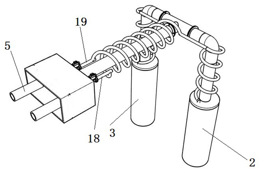
[0029]Embodiment 1, the first water return pipe 18 and the second water return pipe 19 are straight pipes, and the first water return pipe 18 and the second water return pipe 19 are respectively arranged on both sides of the water outlet pipe 16; The outer side of the second water return pipe 19 is evenly provided with heat dissipation fins 22; the heat dissipation fins 22 increase the heat dissipation effect of the first water return pipe 18 and the second water return pipe 19, enhance the heat preservation effect of the water outlet pipe 16, and reduce heat loss.

Embodiment 2

[0030] Embodiment 2, the first return pipe 18 and the second return pipe 19 are spiral pipes, and the first return pipe 18 and the second return pipe 19 are arranged on the periphery of the outlet pipe 16; the heat preservation effect of the outlet pipe 16 is enhanced, Reduced heat loss.

[0031] During the implementation process, the applicant found that turning on and off the first circulation pump 20 and the second circulation pump 21 may cause a large impact on the slider 14; the impact not only causes greater vibration and noise to the system, but also the internal slider 14 The impact in the high-pressure and high-speed system may cause damage to the slider 14 and reduce the reliability of the device. A sliding column 23 is horizontally provided in the reversing cylinder 10, and the slider 14 is provided with a corresponding sliding column. The gap 24; the slider 14 is inlaid with a first magnet 25; the barrier ring 15 is respectively provided with a second magnet 26; th...


PUM


Abstract

The invention discloses a multiple heat exchange system based on deep well heat exchange technology, comprising a well body, a first heat collection tube, a second heat collection tube, and a heat exchange box; the first heat collection tube and the second heat collection tube are completely identical in structure , the first heat collecting tube and the second heat collecting tube are vertically arranged in the well body, the first heat collecting tube includes an outer casing and an inner casing, the upper ends of the outer casing and the inner casing are provided with a sealing plate; the inner casing The upper side passes through the sealing plate and connects with the self-adaptive reversing device; this device adopts a double heat collection mode to provide stable and continuous heat supply to the heat collector end, ensuring continuous heat supply at the heat supply end, and improving a certain heat supply efficiency.

Description

technical field [0001] The invention relates to the field, in particular to a multiple heat exchange system based on deep well heat exchange technology. Background technique [0002] With the increase of human demand for renewable energy, large-scale development and utilization of geothermal energy is imperative, and deep geothermal energy reserves are abundant, which has a huge space for exploitation and utilization. Deep geothermal resources are divided into hydrothermal geothermal energy and dry geothermal energy. Hot rock type geothermal energy; this shows that the earth is a huge heat reservoir, which contains huge heat energy. Geothermal energy is a kind of clean energy and a renewable energy. Its development prospect is very broad. Now, deep well heat exchange technology is used to supply heat to cities in winter. Heat collection pipes are installed in deep wells, and geothermal heat is used to heat the water in the heat collection pipes. Then the heated water is pas...

Claims


Application Information

Patent Timeline
Patent Type & Authority Patents(China)
IPC IPC(8): F24D15/00F24D15/02F24T10/15F28D20/00
CPCF24D15/00F24D15/02F24T10/15F28D20/00Y02E10/10Y02E60/14
Inventor 李成成李成员崔涛王国伟张腾王永强
Owner 北方瑞能(内蒙古)集团有限公司
Why Eureka
Try Eureka